TL100048 TDK Corporation, TL100048 Datasheet
TL100048
Specifications of TL100048


Related parts for TL100048

TL100048 Summary of contents
Page 1
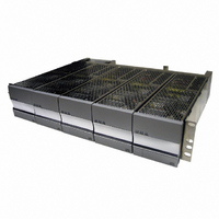
TLR5 Installation, Operation, and Maintenance Manual TLR5 January 2006 Version 1 ...
Page 2
Table of Contents 1) Safety and Recommended Practices General practices 1.1 FCC Compliance Statement 1.2 2) Product Section Heat Dissipation 2.1 AC Requirements 2.2 DC Circuit Drawings 2.3 DC Output Wire Sizing 2.4 Torque Settings 2.5 3) Required Tools 4) ...
Page 3
Safety and Recommended Practices 1.1 General practices For use in restricted access locations only. Suitable for mounting on concrete or other non-combustible surfaces This product accepts a nominal AC voltage between 100 and 240 VAC (±10%), ...
Page 4
TLR5-S S ERIES POWER SYSTEM 1.2 FCC Compliance Statement 1.2.1 Note This device complies with Part 15 of FCC Rules. Operation is subject to the following two conditions: 1. This device may not cause harmful interference, and 2. This device ...
Page 5
... TL75012 Heat Dissipation (24V Power Modules) Model TL50024 TL100024 TL150024 Heat Dissipation (48V Power Modules) Model TL50048 TL100048 TL150048 TL200048 TL250048 3055 Del Sol Blvd • San Diego, CA 92154 • 1-800-LAMBDA-4 TLR5-S S ERIES POWER SYSTEM Typical BTU/hr Max BTU/hr 413 490 ...
Page 6
... Wide Line (100V - 240V) TL50048 TL50024 TL50012 TL75012 TL100048 TL100024 2.2.2 AC Input Types This system utilizes a single, dual, or individual feed AC architecture as shown in Figure 1, Figure 2, & Figure 3 via a rear AC terminal block. The AC architecture can be determined from the model number of the rack. The model number of the rack can be found on the right side, near the rear of the rack ...
Page 7
Single Feed Figure 1 - Single Feed AC Wiring Architecture 2.2.3 AC current and cable sizing A single feed architecture powers all five power modules with a single AC feed. Connect the feed, sized according to section 2.2.3, onto ...
Page 8
TLR5-S S ERIES POWER SYSTEM 2.2.2.2 Dual Feed Figure ual Feed AC Wiring Architecture A dual feed architecture powers power module modules 1, 3, and feed 1, and modules 2 and ...
Page 9
Figure 3 - Individual Feed AC Wiring Architecture An individual feed architecture powers one power module slot per AC feed. Connect the feed, sized according to section 2.2.3, into IEC320 plugs as seen in Figure 9. There are two different ...
Page 10
TLR5-S S ERIES POWER SYSTEM The tables in this section use the absolute minimum input voltage at which the power modules will run at to determine AC requirements corresponds to low line and 180 V corresponds to high ...
Page 11
Recommended AC Circuit Breaker & Wire Sizes (24V system) Fully # of Power Minimum Model # Equiped Modules on Input of Power Rack AC Feed Voltage Module 90 TL50024 Indivudual 180 TL50024 1 90 TL100024 AC feed 180 TL100024 180 ...
Page 12
... TL200048 180 TL250048 90 TL50048 180 TL50048 90 TL100048 Dual 3 180 TL100048 AC feed 180 TL150048 180 TL200048 180 TL250048 90 TL50048 180 TL50048 90 TL100048 4 180 TL100048 180 TL150048 180 TL200048 180 TL250048 90 TL50048 180 TL50048 90 TL100048 Single 5 180 TL100048 AC feed 180 TL150048 180 TL200048 ...
Page 13
AC lugs Table 8 lists part numbers for some lugs you can use to attach your AC wire to the single and dual AC terminal blocks and ground studs. Use the #8 hole lugs for AC terminal block connec- ...
Page 14
TLR5-S S ERIES POWER SYSTEM Each system is equipped with 2 unprotected bulk output connections as shown in Figure 4. Unprotected bulk connections are made with double hole lugs on ¼"-20 studs with 5/8" centers. The maximum tongue width for ...
Page 15
Minumum Recommended DC AWG for 90°C Cabling for Protected Outputs Total Power Module Current Rating ( 100 125 150 175 200 225 250 300 * For wire sizes less than 15 A ...
Page 16
TLR5-S S ERIES POWER SYSTEM Lug Part Number for DC Output Burndy Amp Ring Wire Lug Part Terminal Part AWG # # 16 AWG 321045 14 AWG 321045 12 AWG 323763 10 AWG 323763 10 AWG YAV102TC14 8 AWG YA8CL2TC14 ...
Page 17
Site and Equipment Preparation After removing DC Power Plant from boxes and packing material, inspect for shipping and/or other damage. Have all tools, wire, cables, hardware, etc., within easy reach. To the extent pos- sible ensure a clean (free ...
Page 18
TLR5-S S ERIES POWER SYSTEM 5.2.1 Single Feed For 110 VAC service, connect your line/hot to Line 1, labeled on the AC terminal block shown in Figure 7. Connect your neutral to the slot labeled Line 1/N1. These connections are ...
Page 19
Dual Feed For 110 VAC service, connect your first line/hot to Line 1, labeled on the AC terminal block shown in Figure 8. Connect your neutral to the slot labeled Line 1/N1. For your second feed connect line/hot to ...
Page 20
TLR5-S S ERIES POWER SYSTEM 5.2.3 Individual Feed For any AC service between 100 VAC to 240 VAC connect each line cord into the appropriate AC receptacle on the rear on the rack as seen in Figure ...
Page 21
Figure 11 - Cable routing holes 5.4 DC Reference ground Connect your reference ground to either the negative output or positive output (Figure 10) depending on the desired polarity. The connection is double ¼"-20 studs with 5/8" centers. 5.5 Alarms ...
Page 22
TLR5-S S ERIES POWER SYSTEM 20 10 Figure 12 - Alarm and signal connector on shelf Figure 13 - Alarm cable pin out Page. 22 Revision 1 : January 2006 ...
Page 23
Alarm and Signal Interconnections J1 Wire Description Pin Color 20 BLK Shelf Bias: A regulated 12V/100ma bias supply. Referenced to Pin 10 RED SCL clock line. Referenced to Pin 10 RED/WHT SCL ...
Page 24
TLR5-S S ERIES POWER SYSTEM 6 Test and Turn 6.1 Power up Once all AC and DC connections have been secured and checked, install each power module sequentially by sliding and latching each power module into a rack ...
Page 25
Troubleshooting 7.1 Problems and Solutions The modular, plug-n-play nature of this plant makes diagnostics and repair very easy. Make sure that all power modules are properly seated and latched into their respective slots. Make sure that all power and ...
Page 26
TLR5-S S ERIES POWER SYSTEM 8 Installationsanleitung (German Installation) Eingangsspannung (Voltage): Eingangsspannung (Voltage) Netzteile fuer (100V - 240V) TL50048 TL50024 TL50012 TL50012 TL75048 TL100024 Eingangsstrom (Current ): 75A Nennfrequenz (Frequency): 50/60Hz Modellnummer (Modell No TLXXXX Abmessungen sind nur ...