LK5660-7R POWER ONE, LK5660-7R Datasheet - Page 11
LK5660-7R
Manufacturer Part Number
LK5660-7R
Description
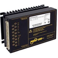
CONVERTER AC/DC 225VIN 48VOUT
Manufacturer
POWER ONE
Series
Kr
Datasheet
1.LK5660-7R.pdf
(29 pages)
Specifications of LK5660-7R
Voltage - Output
24V
Number Of Outputs
2
Power (watts)
150W
Applications
Commercial
Power Supply Type
Switching (Closed Frame)
Voltage - Input
85 ~ 255VAC
Mounting Type
Chassis Mount
1st Output
24 VDC @ 3A
2nd Output
24 VDC @ 3A
Size / Dimension
6.63" L x 4.37" W x 3.15" H (168.5mm x 111mm x 80mm)
Power (watts) - Rated
150W
Operating Temperature
-25°C ~ 71°C
Efficiency
83%
Approvals
CE, cUL, EN, TUV
Output Voltage (channel 1)
24 V
Output Current (channel 1)
3 A
Output Voltage (channel 2)
24 V
Output Current (channel 2)
3 A
Isolation Voltage
2.8 KV
Output Type
Isolated
Lead Free Status / RoHS Status
Contains lead / RoHS non-compliant
3rd Output
-
4th Output
-
Lead Free Status / Rohs Status
Lead free / RoHS Compliant
Other names
LK 5660-7R
LK 5660-7R
Q1660869
LK 5660-7R
Q1660869


Thermal Considerations
If a converter is located in free, quasi-stationary air
(convection cooling) at the indicated maximum ambient
temperature T
and is operated at its nominal input voltage and output
power, the temperature measured at the Measuring point
of case temperature T
the indicated value T
However, the relationship between T
heavily on the conditions of operation and integration into a
system. The thermal conditions are influenced by input
voltage, output current, airflow, and temperature of
surrounding components and surfaces. T
contrary to T
Fig. 12
Output current derating versus temperature for -5, -6, and
-7 (equal to -9) models.
Thermal Protection
A temperature sensor generates an internal inhibit signal,
which disables the outputs, when the case temperature
exceeds T
the temperature drops below this limit.
Continuous operation under simultaneous extreme worst-
case conditions of the following three parameters should
be avoided: Minimum input voltage, maximum output
power, and maximum temperature.
BCD20001-G Rev AC, 16-Dec-2010
Caution: The installer must ensure that under all operating
conditions T
Temperature specifications.
Notes: Sufficient forced cooling or an additional heat sink
(applied to -7 or -9) models allows T
(e.g., 85 °C), if T
in fig. 12, including -5 and -6 models.
I
o
1.0
0.8
0.6
0.4
0.2
/I
0
o nom
C max
convection cooling
C max
C
A max
50
remains within the limits stated in the table:
. The outputs automatically recover, when
, an indicative value only.
C max
(see table: Temperature specifications)
60
C
is not exceeded. Details are specified
(see: Mechanical Data) will approach
C max
-5
70
-6
after the warm-up phase.
forced cooling
80
A
-7
-5
to be higher than 71 °C
-6 -7
90
A
and T
A max
100 °C
T
C max
is therefore,
C
depends
T
A
Page 11 of 29
Output Protection
Each output is protected by a suppressor diode against
overvoltage, which could occur due to a failure of the
control circuit. In such a case, the suppressor diode
becomes a short circuit. The suppressor diodes may
smooth short overvoltages resulting from dynamic load
changes, but they are not designed to withstand externally
applied overvoltages.
A short circuit at any of the two outputs will cause a
shutdown of the other output. A red LED indicates any
overload condition.
Parallel or Series Connection of Converters
Single- or double-output models with equal output voltage
can be connected in parallel without any precautions using
option T (current sharing). If the T pins are interconnected,
all converters share the output current equally.
Single-output models and/or main and second outputs of
double-output models can be connected in series with any
other (similar) output.
Notes:
– Parallel connection of double-output models should always
– Not more than 5 converters should be connected in parallel.
– Series connection of second outputs without involving their
– Series connection of outputs totalizing more than 36 V
– The maximum output current is limited by the output with the
Note: V
voltage is exceeded, the suppressor diode generates losses
and may become a short circuit.
include both, main and second output to maintain good
regulation.
main outputs should be avoided, as regulation may be poor.
nominal voltage need additional measures to limit the output
to SELV (Safe Extra Low Voltage).
lowest current limitation, if several outputs are connected in
series.
150 – 280 Watt AC-DC Converters
o BR
is specified in Electrical Output Data. If this
K Series with PFC Data Sheet
www.power-one.com
Related parts for LK5660-7R
Image
Part Number
Description
Manufacturer
Datasheet
Request
R

Part Number:
Description:
SWITCHING POWER SUPPLIES, SINGLE OUTPUT, 80 WATTS
Manufacturer:
POWER ONE
Datasheet:
Part Number:
Description:
HAS SERIES - 30 WATT
Manufacturer:
POWER ONE
Datasheet:
Part Number:
Description:
SINGLE OUTPUT
Manufacturer:
POWER ONE
Datasheet:

Part Number:
Description:
BRS DC/DC converters(1.5 WATT)
Manufacturer:
Power-One
Datasheet:
Part Number:
Description:
3...15 Watt DC-DC Converter
Manufacturer:
Power-One
Datasheet:
Part Number:
Description:
HBS SERIES - 100 WATT
Manufacturer:
Power-One
Datasheet:
Part Number:
Description:
3...15 Watt DC-DC Converter
Manufacturer:
Power-One
Datasheet:
Part Number:
Description:
BUS DC/DC converters(3 WATT)
Manufacturer:
Power-One
Datasheet:
Part Number:
Description:
HES SERIES 150 WATT
Manufacturer:
Power-One
Datasheet:
Part Number:
Description:
1.25 WATT
Manufacturer:
Power-One
Datasheet: