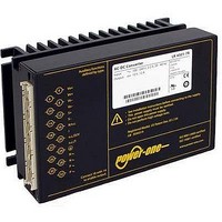
LK5660-7R POWER ONE, LK5660-7R Datasheet - Page 14

LK5660-7R
Manufacturer Part Number
LK5660-7R
Description
CONVERTER AC/DC 225VIN 48VOUT
Manufacturer
POWER ONE
Series
Kr
Datasheet
1.LK5660-7R.pdf
(29 pages)
Specifications of LK5660-7R
Voltage - Output
24V
Number Of Outputs
2
Power (watts)
150W
Applications
Commercial
Power Supply Type
Switching (Closed Frame)
Voltage - Input
85 ~ 255VAC
Mounting Type
Chassis Mount
1st Output
24 VDC @ 3A
2nd Output
24 VDC @ 3A
Size / Dimension
6.63" L x 4.37" W x 3.15" H (168.5mm x 111mm x 80mm)
Power (watts) - Rated
150W
Operating Temperature
-25°C ~ 71°C
Efficiency
83%
Approvals
CE, cUL, EN, TUV
Output Voltage (channel 1)
24 V
Output Current (channel 1)
3 A
Output Voltage (channel 2)
24 V
Output Current (channel 2)
3 A
Isolation Voltage
2.8 KV
Output Type
Isolated
Lead Free Status / RoHS Status
Contains lead / RoHS non-compliant
3rd Output
-
4th Output
-
Lead Free Status / Rohs Status
Lead free / RoHS Compliant
Other names
LK 5660-7R
LK 5660-7R
Q1660869
LK 5660-7R
Q1660869
Fig. 21
Output voltage control for single-output models
Table 10: R
Table 10b: R’
BCD20001-G Rev AC, 16-Dec-2010
1
V
Notes:
– The R-Function excludes option P (output voltage
– With double-output models the second output follows the
– In case of parallel connection the output voltages should be
V
V
First column: V
o
o
V
o nom
0.5
1.0
1.5
2.0
2.5
3.0
3.5
4.0
4.5
5.0
5.15
5.2
5.25
5.3
5.35
5.4
5.45
5.5
adjustment by potentiometer).
If the output voltages are increased above V
control, option P setting, remote sensing, or option T, the
output currents should be reduced, so that P
exceeded.
value of the controlled main output.
individually set within a tolerance of 1 – 2%.
o nom
[V]
[V]
= 5.1 V
= 5.1 V
R'
ext
R
200
432
215
147
110
14.7
30.1
N~
N~
ext
ext
ext
L~
L~
88.7
75
64.9
57.6
0.432
0.976
1.65
2.61
3.83
5.76
8.66
for V
for V
[k ]
[k ]
o
or V
o
< V
o
> V
o1
; second column: double-output models with outputs in series connection
o nom
12.5
12.7
12.8
12.1
12.2
12.3
12.4
12.6
13.0
13.2
10
11
o nom
2
3
4
5
6
7
8
9
06003a
; approximate values (V
V
V
V
; approximate values (V
o
o
o nom
V
16
14
12
16
14
[V]
[V]
o nom
Vo1+
R
S–
Vo1–
Vo1+
S+
R
S–
Vo1–
1
24.2
24.4
24.6
24.8
25.0
25.2
25.4
25.6
26.0
26.4
1
= 12 V
10
12
14
16
18
20
22
4
6
8
= 12 V
+
o nom
R'
R
V
R'
R
1820
ext
ext
ext
12.1
20
42.2
ext
931
619
475
383
316
274
243
196
169
ext
o nom
0.806
1.33
2
2.87
4.02
5.62
8.06
via R-input
[k ]
[k ]
is not
i nom
Page 14 of 29
i nom
, I
15.2
15.4
15.6
15.8
16.0
16.2
16.4
16.5
10
11
12
13
14
, I
o nom
2
4
6
8
9
o nom
V
V
Fig. 22
Double-output models:
Wiring of the R-input for output voltages 24 V, 30 V, or
48 V with both outputs in series. A ceramic capacitor (C
across the load reduces ripple and spikes.
Test Jacks
Test jacks (pin diameter 2 mm) for measuring the main
output voltage V
converter. The positive test jack is protected by a series
resistor (see: Functional Description, block diagrams).
The voltage measured at the test jacks is slightly lower
than the value at the output terminals.
V
, series E 96 resistors); R'
o
Vo2+
Vo2+
Vo2–
Vo2–
Vo1+
Vo1–
o
V
o nom
, series E 96 resistors); R
[V]
[V]
o nom
R
1
30.4
30.8
31.2
31.6
32.0
32.4
32.8
33.0
1
= 15 V
12
16
18
20
22
24
26
28
150 – 280 Watt AC-DC Converters
14
4
8
10
12
16
= 15 V
4
6
8
R
ext
K Series with PFC Data Sheet
R'
R
1500
ext
ext
11
16.2
26.1
56.2
768
523
392
316
267
232
221
o
0.619
1.47
2.67
4.53
6.04
8.06
[k ]
[k ]
or V
V
o1
o1
R'
24 V
30 V
48 V
ext
are located at the front of the
ext
10
12
14
16
18
20
22
24.25
24.5
24.75
25.0
25.25
25.5
25.75
26.0
26.25
26.4
ext
4
6
8
= not fitted
= not fitted
V
V
V
o nom
o
o
V
[V]
[V]
o nom
06004a
= 24 V
1
48.5
49.0
49.5
50.0
50.5
51.0
51.5
52.0
52.5
52.8
1
20
24
40
44
12
16
28
32
36
www.power-one.com
8
= 24 V
R'
R
12.1
20
44.2
ext
ext
3320
1690
1130
0.806
2
2.87
4.02
5.62
8.06
1.33
845
698
590
511
442
402
383
[k ]
[k ]
C
o
o
+
–
)


