LK5660-7R POWER ONE, LK5660-7R Datasheet - Page 13
LK5660-7R
Manufacturer Part Number
LK5660-7R
Description
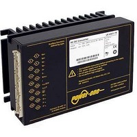
CONVERTER AC/DC 225VIN 48VOUT
Manufacturer
POWER ONE
Series
Kr
Datasheet
1.LK5660-7R.pdf
(29 pages)
Specifications of LK5660-7R
Voltage - Output
24V
Number Of Outputs
2
Power (watts)
150W
Applications
Commercial
Power Supply Type
Switching (Closed Frame)
Voltage - Input
85 ~ 255VAC
Mounting Type
Chassis Mount
1st Output
24 VDC @ 3A
2nd Output
24 VDC @ 3A
Size / Dimension
6.63" L x 4.37" W x 3.15" H (168.5mm x 111mm x 80mm)
Power (watts) - Rated
150W
Operating Temperature
-25°C ~ 71°C
Efficiency
83%
Approvals
CE, cUL, EN, TUV
Output Voltage (channel 1)
24 V
Output Current (channel 1)
3 A
Output Voltage (channel 2)
24 V
Output Current (channel 2)
3 A
Isolation Voltage
2.8 KV
Output Type
Isolated
Lead Free Status / RoHS Status
Contains lead / RoHS non-compliant
3rd Output
-
4th Output
-
Lead Free Status / Rohs Status
Lead free / RoHS Compliant
Other names
LK 5660-7R
LK 5660-7R
Q1660869
LK 5660-7R
Q1660869


Auxiliary Functions
Inhibit for Remote On/Off
The outputs may be enabled or disabled by means of a
logic signal (TTL, CMOS, etc.) applied between the inhibit
input i (pin 18) and pin 14 (S– or Vo1–). In systems with
several converters, this feature can be used to control the
activation sequence of the converters. If the inhibit function
is not required, connect the inhibit pin 18 to pin 14.
Fig. 18
Definition of V
Table 8: Inhibit characteristics
Fig. 19
Typical inhibit current I
Fig. 20
Output response as a function of inhibit control
BCD20001-G Rev AC, 16-Dec-2010
Characteristic
V
I
t
t
Note: If pin 18 is not connected, the output is disabled.
inh
r
f
inh
–0.4
–0.8
I
2.0
1.6
1.2
0.8
0.4
inh
Inhibit
voltage
Inhibit current
Rise time
Fall time
0
–50
V
0.1
[mA]
o
Inhibit
1
0
1
0
/V
o nom
inh
V
V
o
o
–30
V
V
= on
= off
and I
inh
o
= on
= 0.8 V
t
r
inh
Conditions
V
V
inh
–10
.
i min
inh
versus inhibit voltage V
S–/Vo1–
= 0
– V
06031b
Vo+
0
i max
depending on I
i
10
18
14
V
inh
min
– 50
2.4
= 2.4 V
V
I
V
inh
30
inh
t
o
f
typ
30
= off
o
– 400 µA
max Unit
0.8
50
50
06001
inh
t
t
V
inh
ms
Page 13 of 29
V
[V]
Sense Lines (Single-Output Models)
This feature allows for compensation of voltage drops
across the connector contacts and if necessary, across the
load lines. We recommend connecting the sense lines
directly at the female connector.
To ensure correct operation, both sense lines (S+, S–)
should be connected to their respective power outputs
(Vo+ and Vo–), and the voltage difference between any
sense line and its respective power output (as measured
on the connector) should not exceed the following values:
Table 9: Maximum voltage compensation allowed using
sense lines
Programmable Output Voltage (R-Function)
As a standard feature, the converters offer an adjustable
output voltage, identified by letter R in the type
designation. The control input R (pin 16) accepts either a
control voltage V
output voltage. When input R is not connected, the output
voltage is set to V
a) Adjustment by means of an external control voltage V
b) Adjustment by means of an external resistor:
Warning:
12 V, 15 V, 24 V
Important: Sense lines must always be connected!
Incorrectly
overvoltage protection resulting in a permanent short-circuit
of the output.
Note: If the output voltages are increased above V
R-input control, option P setting, remote sensing or option T,
the output currents must be reduced accordingly, so that
P
between pin 16 (R) and pin 14:
The control voltage range is 0 – 2.75 VDC and allows an
output voltage adjustment in the range of approximately
0 – 110% V
Depending upon the value of the required output voltage
the resistor shall be connected
either: Between pin 16 and pin 14 (V
achieve an output voltage adjustment range of approxi-
mately 0 – 100% V
or: Between pin 16 and pin 12 (V
output voltage adjustment range of 100 – 110% V
– V
– The value of R'
V
o nom
ext
Output
voltage
value as indicated in table R'
prevent the converter from damage!
5.1 V
ext
150 – 280 Watt AC-DC Converters
is not exceeded.
–––––– • 2.5 V
shall never exceed 2.75 V.
V
o nom
V
o
connected
K Series with PFC Data Sheet
o nom
between sense lines and
ext
their respective outputs
Total voltage difference
o nom
.
ext
or a resistor R
o nom
shall never be less than the lowest
.
sense
0.5 V
1.0 V
.
lines
ext
ext
o
> V
to adjust the desired
(for V
may
o nom
www.power-one.com
Voltage difference
0
Vo– and S–
o
) to achieve an
activate
between
0.25 V
0.25 V
V
0 nom
V
o nom
o nom
o nom
) to
via
the
.
) to
ext
Related parts for LK5660-7R
Image
Part Number
Description
Manufacturer
Datasheet
Request
R

Part Number:
Description:
SWITCHING POWER SUPPLIES, SINGLE OUTPUT, 80 WATTS
Manufacturer:
POWER ONE
Datasheet:
Part Number:
Description:
HAS SERIES - 30 WATT
Manufacturer:
POWER ONE
Datasheet:
Part Number:
Description:
SINGLE OUTPUT
Manufacturer:
POWER ONE
Datasheet:

Part Number:
Description:
BRS DC/DC converters(1.5 WATT)
Manufacturer:
Power-One
Datasheet:
Part Number:
Description:
3...15 Watt DC-DC Converter
Manufacturer:
Power-One
Datasheet:
Part Number:
Description:
HBS SERIES - 100 WATT
Manufacturer:
Power-One
Datasheet:
Part Number:
Description:
3...15 Watt DC-DC Converter
Manufacturer:
Power-One
Datasheet:
Part Number:
Description:
BUS DC/DC converters(3 WATT)
Manufacturer:
Power-One
Datasheet:
Part Number:
Description:
HES SERIES 150 WATT
Manufacturer:
Power-One
Datasheet:
Part Number:
Description:
1.25 WATT
Manufacturer:
Power-One
Datasheet: