FPSS1U TDK Corporation, FPSS1U Datasheet - Page 36
FPSS1U
Manufacturer Part Number
FPSS1U
Description
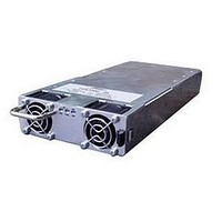
RACK 3 SLOT FOR FPS1000
Manufacturer
TDK Corporation
Series
FPSr
Specifications of FPSS1U
Accessory Type
Rack System
No. Of Slots
3
Peak Reflow Compatible (260 C)
No
External Width
19.00"
Rack U Height
1
External Depth
13.82"
For Use With
285-1239 - PWR SUP FNT END 48V 1008W 21A285-1238 - PWR SUP FNT END 32V 992W 31A285-1237 - PWR SUP FNT END 24V 960W 40A
Lead Free Status / RoHS Status
Lead free / RoHS Compliant
For Use With/related Products
FPS1000 Series
Lead Free Status / Rohs Status
RoHS Compliant part
Other names
285-1240
Available stocks
Company
Part Number
Manufacturer
Quantity
Price
Company:

Part Number:
FPSS1U
Manufacturer:
TDK-LAMBDA
Quantity:
232
Company:
Part Number:
FPSS1U/P
Manufacturer:
TDK-LAMBDA
Quantity:
232


12.4 On/Off control
Fig 12-4 shows typical connection for individual On/Off control of each installed FPS1000 unit. The On/Off
control signal is applied to the DB25 connector located at the rear panel (refer to sec. 10.7.5).
When it is desired to control all the installed units simultaneously, it is possible to connect the On/Off control
as shown in Fig 12-5.
Fig 12-4: Individual On/Off control
12.5 Output voltage trimming
Refer to Fig 12-6 for output voltage trimming typical application.
12.6 Supervisory signals
Supervisory signals are accessible at the J1-DB25 female connector on the rear panel of the rack.
Fig 12-7 shows a typical connection for FPS1000 unit "A" inside the rack.
Units "B" and "C" connections - Reffer to sec 10.7.5.
12.7 Grounding outputs
Either the positive or negative output terminals can be grounded. To avoid noise problems caused by
common-mode current flowing from the load to ground, it is recommended to ground the output terminal
as close as possible to the power supply's output. Always use two wires to connect the load to the power
supply regardless of how the system is grounded.
FPS-S1U
Note: AC_FAIL, DC_OK and TEMP.ALARM are open collector signals.
Fig 12-7: Supervisory signals
Fig 12-6: Output voltage trimming
FPS-S1U
FPS-1000
Module A
FPS-1000 Module B
FPS-1000 Module C
FPS-S1U
SIGNAL_RET
ON/OFF_A
ON/OFF_B
ON/OFF_C
TEMP.ALARM_A
V_TRIM_A
V_TRIM_B
V_TRIM_C
SIGNAL RET
AC_FAIL_A
DC_OK_A
12V AUX
15
25
11
+S
5
-S
ON/
OFF
UNIT
‘C’
13
7
1
10
22
ON/
OFF
(J1)
16
11
8
6
4
UNIT
+V
-V
‘B’
10K
ON/
OFF
UNIT
‘A’
10K
R1
R2
10K
FPS-S1U
Fig 12-5: Single On/Off control
FPS-S1U with FPS1000-12 installed:
R2=0.0324*V
R1(K Ω )=5(K Ω )-R2(K Ω )
FPS-S1U with FPS1000-24 installed:
R2=0.0785*V
R1(K Ω )=20(K Ω )-R2(K Ω )
FPS-S1U with FPS1000-32 installed:
R2=0.0463*V
FPS-S1U with FPS1000-48 installed:
R2=0.0497*V
R1(K Ω )=50(K Ω )-R2(K Ω )
R1(K Ω )=20(K Ω )-R2(K Ω Ω)
Application
Monitoring
and Control
circuts
33
SIGNAL_RET
ON/OFF_A
ON/OFF_B
ON/OFF_C
2
2
2
2
out
out
out
out
-7.2795*V
-1.1298*V
-5.819*V
-4.5805*V
15
25
11
5
ON/
OFF
out
out
FPS-S1U Instruction Manual
out
out
+105.132
+259.04
+9.9342
+109.49
Related parts for FPSS1U
Image
Part Number
Description
Manufacturer
Datasheet
Request
R

Part Number:
Description:
KIT F-SERIES CLIPS
Manufacturer:
PHIHONG USA
Datasheet:

Part Number:
Description:
TDK DC to DC Converters, DC to AC Inverters
Manufacturer:
TDK Corporation
Datasheet:
Part Number:
Description:
TDK DC to DC Converters, DC to AC Inverters
Manufacturer:
TDK Corporation
Datasheet: