P0302 Terasic Technologies Inc, P0302 Datasheet
P0302
Specifications of P0302
Available stocks


Related parts for P0302


P0302 Summary of contents
Page 1
USB-Blaster Download Cable 101 Innovation Drive San Jose, CA 95134 www.altera.com UG-USB81204-2.3 P25-10325-03 User Guide Document Version: Document Date: May 2007 2.3 ...
Page 2
Copyright © 2007 Altera Corporation. All rights reserved. Altera, The Programmable Solutions Company, the stylized Altera logo, specific device des- ignations, and all other words and logos that are identified as trademarks and/or service marks are, unless noted otherwise, the ...
Page 3
Chapter 1. Setting Up the USB-Blaster Download Cable Introduction ............................................................................................................................................ 1–1 Device Support ................................................................................................................................. 1–1 Power Requirements ........................................................................................................................ 1–1 Software Requirements ................................................................................................................... 1–2 Hardware Setup ..................................................................................................................................... 1–2 Software Setup ....................................................................................................................................... 1–3 Installing the USB-Blaster Driver on Windows 2000 and Windows ...
Page 4
Contents iv USB-Blaster Download Cable User Guide Altera Corporation ...
Page 5
Revision History The table below displays the revision history for the chapters in this User Guide. Date Version May 2007 2.3 ● ● ● ● ● March 2007 2.2 Update to Systems” July 2006 2.1 Minor update to Chapter 2. ...
Page 6
How to Contact Altera How to Contact For the most up-to-date information about Altera products, refer to the following table. Altera Technical support Technical training Product literature Altera literature services Non-technical support (General) Note to table: (1) Typographic This document ...
Page 7
About this User Guide Visual Cue Courier type Signal and port names are shown in lowercase Courier type. Examples: tdi Anything that must be typed exactly as it appears is shown in Courier type. For example: actual file, such as ...
Page 8
Typographic Conventions viii USB-Blaster Download Cable User Guide Preliminary Altera Corporation ...
Page 9
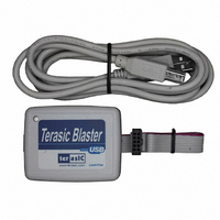
Introduction The USB-Blaster™ download cable interfaces a USB port on a host computer to an Altera cable sends configuration data from the standard 10-pin header connected to the FPGA. You can use the USB-Blaster cable to iteratively ...
Page 10
Hardware Setup Software Requirements The USB-Blaster download cable is only available for Windows 2000, Windows XP, and Linux systems. Use the Quartus The USB-Blaster download cable also supports the following: ■ ■ ■ ■ Hardware Setup This section describes how ...
Page 11
Setting Up the USB-Blaster Download Cable Figure 1–1. The USB-Blaster Download Cable 10-pin Female Connector (connects to target printed circuit board 10-pin male header Software Setup This section describes the following: ■ ■ Installing the USB-Blaster Driver on ...
Page 12
Software Setup To install the driver, follow the directions below 10. Click Finish in the Completing the Add/Remove Hardware Wizard Installing the USB-Blaster Driver on Linux This section describes how ...
Page 13
Setting Up the USB-Blaster Download Cable # # Altera USB-Blaster # usbblaster 0x03 0x09fb 0x6001 0x0 0x0 0x0 0x0 0x0 0x0 0x0 0x0 0x0 usbblaster 0x03 0x09fb 0x6002 0x0 0x0 0x0 0x0 0x0 0x0 0x0 0x0 0x0 usbblaster 0x03 0x09fb ...
Page 14
Software Setup Figure 1–2. Hardware Setup Dialog Box Table 1–1. Programming Modes Joint Test Action Group (JTAG) In-Socket Programming Passive Serial Programming Configures all Altera devices supported by Active Serial Programming 1–6 USB-Blaster Download Cable User ...
Page 15
Setting Up the USB-Blaster Download Cable f For details about programming devices and creating secondary programming files, see the Programming & Configuration chapter of the Introduction to Quartus II Handbook. For further information, see the Programming module of the Quartus ...
Page 16
Software Setup 1–8 USB-Blaster Download Cable User Guide Altera Corporation May 2007 ...
Page 17
Overview This chapter provides comprehensive information about the USB-Blaster ■ ■ ■ USB-Blaster The USB-Blaster cable has a USB universal plug that connects to the PC USB port, and a 10-pin female plug that connects to the circuit board. Data ...
Page 18
USB-Blaster Connections Table 2–1. USB-Blaster VCC(TRGT) Pin Voltage Requirements EPC2 device EPC4, EPC8, and EPC16 devices EPCS1, EPCS4, EPCS16, and EPCS64 devices Cable-to-Board Connection A standard USB cable connects to the USB port on the device. shows a block diagram ...
Page 19
Figure 2–2. USB-Blaster 10-Pin Female Plug Dimensions Table 2–2 corresponding programming mode. Table 2–2. USB-Blaster Female Plug Signal Names & Programming Modes AS Mode Pin Signal Name Description DCLK 1 Clock signal GND 2 Signal ground CONF_DONE 3 Configuration done ...
Page 20
Operating Conditions 1 Circuit Board Header Connection The circuit board's 10-pin male header, which connects to the USB-Blaster cable's 10-pin female plug, has two rows of five pins. These pins are connected to the device’s programming or configuration pins. shows ...
Page 21
Table 2–4. USB-Blaster Cable Recommended Operating Conditions Symbol Parameter V Target supply voltage, 5.0-V operation CC(TRGT) Target supply voltage, 3.3-V operation Target supply voltage, 2.5-V operation Target supply voltage, 1.8-V operation Target supply voltage, 1.5-V operation Table 2–5. USB-Blaster Cable ...
Page 22
USB-Revision Table 2–6. USB-Blaster Cable (Rev Operating Conditions Symbol Parameter V High-level input voltage IH V Low-level input voltage IL V 5.0-V high-level output voltage V OH 3.3-V high-level output voltage V 2.5-V high-level output voltage V 1.8-V ...
Page 23
References For more information on configuration and in-system programmability (ISP), see the following sources: ■ ■ ■ ■ ■ ■ ■ ■ ■ ■ ■ ■ Altera Corporation May 2007 USB-Blaster Download Cable User Guide AN 39: IEEE 1149.1 (JTAG) ...
Page 24
References 2–8 USB-Blaster Download Cable User Guide Altera Corporation May 2007 ...