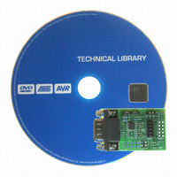
ATADAPCAN01 Atmel, ATADAPCAN01 Datasheet

ATADAPCAN01
Specifications of ATADAPCAN01
Available stocks
Related parts for ATADAPCAN01
ATADAPCAN01 Summary of contents
Page 1
... ATADAPCAN01 - STK501 CAN Extension The ATADAPCAN01 - STK501 CAN add- extension to the STK500 and STK501 development boards from Atmel Corporation, adding support for the AVR AT90CAN128 device in a single development environment. The AVR AT90CAN128 includes a built-in Controller Area Network (CAN) controller with all the features required to implement the CAN serial communication protocol in accordance with the “ ...
Page 2
... Flat-cable connection to PORTD. Using a 10-wire flat-cable provided with the STK500 kit, connect the PORTD header of the STK500 to the PORTD header of the ATADAPCAN01, as shown in figure 1. Care should be taken to use the correct pin orientation. Figure 1. Connecting to the STK500 through a 10-wire flat-cable ATADAPCAN01 Direct mounting onto PORTD ...
Page 3
... CAN bus from the STK500 / ATADAPCAN01 ground. To function correctly, a CAN bus requires 120 ohm termination on both ends. The ATADAPCAN01 can become a terminated node on the CAN bus simply by setting the jumper labelled "TERM". This terminates the CAN bus with two series-connected 62 ohm resistors. Setting the jumper labelled " ...
Page 4
... Figure 2. Component Placement Many CAN transceiver devices available have various extra functions accessible through pins 5 and 8. The ATADAPCAN01 allows you to take advantage of some of these features. Pin 8 on both "CAN1" and "CAN2" footprints are connected centre pin of the "SLOPE CTRL" connector. Pin 5 of "CAN1" is connected to the centre-tap of the ter- mination network, and pin 5 of " ...
Page 5
Figure 3. Schematic Layout AT90CAN128 5 ...
Page 6
... No licenses to patents or other intellectual property of Atmel are granted by the Company in connection with the sale of Atmel products, expressly or by implication. Atmel’s products are not authorized for use as critical components in life support devices or systems. ...


