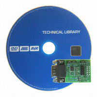
ATADAPCAN01 Atmel, ATADAPCAN01 Datasheet - Page 3

ATADAPCAN01
Manufacturer Part Number
ATADAPCAN01
Description
EXTENSION CAN ADD-ON TO STK500/1
Manufacturer
Atmel
Datasheet
1.ATADAPCAN01.pdf
(6 pages)
Specifications of ATADAPCAN01
Accessory Type
CAN Adapter
Product
Microcontroller Modules
Data Bus Width
8 bit
Core Processor
AT90CAN128
Interface Type
RS-232
Board Size
50 mm x 32 mm
For Use With/related Products
STK500, STK501
Lead Free Status / RoHS Status
Lead free / RoHS Compliant
Available stocks
Company
Part Number
Manufacturer
Quantity
Price
Company:
Part Number:
ATADAPCAN01
Manufacturer:
Atmel
Quantity:
135
CAN Bus Interface
BUS Connectors
CAN BUS Grounding and
Shielding
CAN BUS Termination
CAN Transceiver Options
3
AT90CAN128
Several options are available to physically connect the ATADAPCAN01 to a CAN bus.
The D-SUB-9 MALE connector is the primary connection point to a CAN bus. Alterna-
tively, the 10-pin header labelled "CAN BUS flat-cable" can be used, or both connectors
can be used if the CAN bus topology requires it. Both connectors are wired according to
CiA Draft Standard 102 version 2.0 as shown in table 1.
Table 1. CAN Bus Connector Wiring
Note:
The "CAN_SHLD" signal in each of the two CAN bus connectors can be optionally con-
nected to ground by mounting 0 ohm or small value resistors in positions R2 (for D-SUB-
9) and R3 (for flat-cable). The landing pads of both R2 and R3 are 1206 standard size.
By default, the "CAN_GND" signals in both connectors are wired to the STK500 ground
through 0 ohm resistor R1. Removing R1 will isolate the "CAN_GND" ground signals on
the CAN bus from the STK500 / ATADAPCAN01 ground.
To function correctly, a CAN bus requires 120 ohm termination on both ends. The
ATADAPCAN01 can become a terminated node on the CAN bus simply by setting the
jumper labelled "TERM". This terminates the CAN bus with two series-connected 62
ohm resistors. Setting the jumper labelled "SPLIT" connects the centre-tap between
these two resistors to ground through 10nF capacitor C1. This reduces common-mode
noise on the bus line. This centre tap can also be stabilised as described later in the
”Split voltage” section (if supported by the CAN transceiver mounted in "CAN1").
The ATADAPCAN01 board has two CAN transceiver footprints. This is to facilitate easy
evaluation of alternate CAN devices as well as to provide access to various extra fea-
tures of some of these parts. Refer to the schematic diagram in Figure 2 (below) while
considering these options.
Both "CAN1" and "CAN2" footprints use standard CAN device pinouts for pins 1, 2, 3, 4,
6 and 7. By default, "CAN1" is mounted on the board (Atmel ATA6660). To use a device
in "CAN2", solder the device to the board, and remove the 0 ohm ’resistors’ labelled R8,
R9 R10 from the "CAN1" section, and mount them into the "CAN2" section in positions
R11, R12, R13. Although it is acceptable that idle CAN transceivers remain attached to
the CAN bus, only one CAN device should be connected to the AVR device at any time.
Signal Description
Reserved
CAN_L
CAN_GND
Reserved
CAN_SHLD*
CAN_GND
CAN_H
Reserved
CAN_V+
(not used)
1. CAN_SHLD pins are not connected together internally
D-SUB-9 pin
5
1
2
3
4
6
7
8
9
(1)
Flat-cable Pin
9
10
1
3
5
7
2
4
6
8
(1)
4330B–CAN–03/04


