MA240017 Microchip Technology, MA240017 Datasheet - Page 61
MA240017
Manufacturer Part Number
MA240017
Description
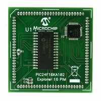
MODULE PLUG-IN PIC24F16KA102 PIM
Manufacturer
Microchip Technology
Series
PIC®r
Specifications of MA240017
Accessory Type
Plug-In Module (PIM) - PIC24F16KA102
Product
Microcontroller Modules
Data Bus Width
16 bit
Core Processor
PIC24F16KA102
Operating Supply Voltage
3 V to 3.6 V
Development Tools By Supplier
Integrated Development Environment, Assembler, ANSI C Compiler
Processor Series
PIC24F
Silicon Manufacturer
Microchip
Core Architecture
PIC
Core Sub-architecture
PIC24
Silicon Core Number
PIC24F
Silicon Family Name
PIC24FxxKAxx
Lead Free Status / RoHS Status
Lead free / RoHS Compliant
For Use With/related Products
Explorer 16 (DM240001 or DM240002)
For Use With
DM240001 - BOARD DEMO PIC24/DSPIC33/PIC32
Lead Free Status / Rohs Status
Lead free / RoHS Compliant
Available stocks
Company
Part Number
Manufacturer
Quantity
Price
Company:

Part Number:
MA240017
Manufacturer:
MICROCHIP
Quantity:
12 000


REGISTER 7-1:
TABLE 7-1:
7.1
If clock switching is enabled, the system clock source at
device Reset is chosen as shown in Table 7-2. If clock
switching is disabled, the system clock source is always
selected according to the oscillator Configuration bits.
Refer to Section 8.0 “Oscillator Configuration” for
further details.
© 2009 Microchip Technology Inc.
bit 1
bit 0
Note 1:
TRAPR (RCON<15>)
IOPUWR (RCON<14>)
CM (RCON<9>)
EXTR (RCON<7>)
SWR (RCON<6>)
WDTO (RCON<4>)
SLEEP (RCON<3>)
IDLE (RCON<2>)
BOR (RCON<1>)
POR (RCON<0>)
DPSLP (RCON<10>)
Note:
2:
Clock Source Selection at Reset
All Reset flag bits may be set or cleared by the user software.
Flag Bit
All of the Reset status bits may be set or cleared in software. Setting one of these bits in software does not
cause a device Reset.
If the FWDTEN Configuration bit is ‘1’ (unprogrammed), the WDT is always enabled, regardless of the
SWDTEN bit setting.
BOR: Brown-out Reset Flag bit
1 = A Brown-out Reset has occurred (the BOR is also set after a POR)
0 = A Brown-out Reset has not occurred
POR: Power-on Reset Flag bit
1 = A Power-up Reset has occurred
0 = A Power-up Reset has not occurred
RESET FLAG BIT OPERATION
RCON: RESET CONTROL REGISTER
Trap Conflict Event
Illegal Opcode or Uninitialized W Register Access
Configuration Mismatch Reset
MCLR Reset
RESET Instruction
WDT Time-out
PWRSAV #SLEEP Instruction
PWRSAV #IDLE Instruction
POR, BOR
POR
PWRSAV #SLEEP instruction with DSCON <DSEN> set
Preliminary
Setting Event
PIC24F16KA102 FAMILY
TABLE 7-2:
Reset Type
(1)
WDTO
MCLR
SWR
POR
BOR
(CONTINUED)
FNOSC Configuration bits
(FNOSC<10:8>)
COSC Control bits
(OSCCON<14:12>)
OSCILLATOR SELECTION vs.
TYPE OF RESET (CLOCK
SWITCHING ENABLED)
Clock Source Determinant
PWRSAV Instruction, POR
Clearing Event
DS39927B-page 59
POR
POR
POR
POR
POR
POR
POR
POR
—
—
Related parts for MA240017
Image
Part Number
Description
Manufacturer
Datasheet
Request
R

Part Number:
Description:
Manufacturer:
Microchip Technology Inc.
Datasheet:
Part Number:
Description:
Manufacturer:
Microchip Technology Inc.
Datasheet:
Part Number:
Description:
Manufacturer:
Microchip Technology Inc.
Datasheet:
Part Number:
Description:
Manufacturer:
Microchip Technology Inc.
Datasheet:
Part Number:
Description:
Manufacturer:
Microchip Technology Inc.
Datasheet:
Part Number:
Description:
Manufacturer:
Microchip Technology Inc.
Datasheet:
Part Number:
Description:
Manufacturer:
Microchip Technology Inc.
Datasheet:
Part Number:
Description:
Manufacturer:
Microchip Technology Inc.
Datasheet: