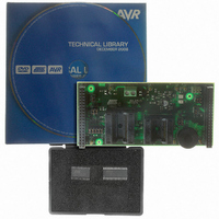
ATSTK520 Atmel, ATSTK520 Datasheet - Page 15

ATSTK520
Manufacturer Part Number
ATSTK520
Description
ADAPTER KIT FOR 90PWM
Manufacturer
Atmel
Datasheet
1.ATSTK520.pdf
(24 pages)
Specifications of ATSTK520
Accessory Type
STK500 Expansion Module
Silicon Manufacturer
Atmel
Core Architecture
AVR
Silicon Core Number
AT90PWM2, AT90PWM3
Kit Contents
Board Cable Docs
Rohs Compliant
Yes
For Use With/related Products
24-Pin and 32-Pin AT90PWM AVR Devices
For Use With
ATSTK500 - PROGRAMMER AVR STARTER KIT
Lead Free Status / RoHS Status
Lead free / RoHS Compliant
Available stocks
Company
Part Number
Manufacturer
Quantity
Price
Company:
Part Number:
ATSTK520
Manufacturer:
Atmel
Quantity:
135
STK520 User Guide
Table 3-1. Troubleshooting Guide
Note:
Problem
Serial Programming
does not work
Parallel Programming
does not work.
Emulation does not
work.
1. See the application note “AVR065: LCD Driver for the STK520 LCD” on how to con-
trol the LCD-display or the the application note “AVR064: STK520 – A Temperature
Monitoring System with LCD Output”.
Reason
ISP cable not connected.
STK500 target voltage
error.
The RSTDISBL Fuse is
programmed.
Cables not connected
properly.
STK500 target voltage
error.
ISP cable not connected.
Conflict with STK500
Reset
DWEN fuse is not
programmed
The RSTDISBL Fuse is
programmed.
Troubleshooting Guide
Solution
Connect the ISP cable according to
Figure 2-4.
Please refer to the AT90PWM3
datasheet for the Serial
Programming Voltage limits. Adjust
the target voltage on the STK500
board accordingly.
Use Parallel Programming to
unprogram the RSTDISBL Fuse.
Please refer to Figure 2-5 for
correct Parallel Programming setup.
Please refer to the AT90PWM3 data
sheet for the Parallel Programming
Voltage limits. Adjust the target
voltage on the STK500 board
accordingly.
Connect the ISP cable according to
Figure 2-7.
Remove Reset Jumper on STK500
Board
Please set the DWEN bit using
parallel programming
Use Parallel Programming to
unprogram the RSTDISBL Fuse.
Section 3
Rev. 7510A–AVR–08/05
3-14


