STEVAL-ILL025V1 STMicroelectronics, STEVAL-ILL025V1 Datasheet
STEVAL-ILL025V1
Specifications of STEVAL-ILL025V1
Available stocks


Related parts for STEVAL-ILL025V1


STEVAL-ILL025V1 Summary of contents
Page 1
... STEVAL-ILL024V1 and STEVAL-ILL025V1 demonstration boards based on the STP16DP05 LED matrix driver and STM32F103VB Introduction This user manual describes the operation of the STM32F103VB-based LED matrix display demonstration board. This board demonstrates the capability of the STP16DP05 LED driver to drive the matrix LED panel. The complete system includes one master board, one slave board and LED matrix display panels ...
Page 2
... System description . . . . . . . . . . . . . . . . . . . . . . . . . . . . . . . . . . . . . . . . . . 7 2.1 Description of the STEVAL-ILL024V1 microcontroller-based control unit . 7 2.1.1 2.1.2 2.2 Description of the STEVAL-ILL025V1 LED driver-based display unit . . . . 8 3 System configuration . . . . . . . . . . . . . . . . . . . . . . . . . . . . . . . . . . . . . . . 10 3.1 One control unit and one display unit configuration . . . . . . . . . . . . . . . . . 10 3.2 Two control units and one display unit configuration . . . . . . . . . . . . . . . . 11 3.3 Multiple control and display unit configuration ...
Page 3
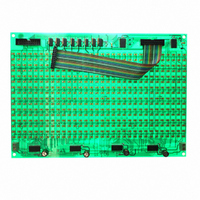
... UM0767 List of figures Figure 1. STEVAL-ILL025V1, LED display panel . . . . . . . . . . . . . . . . . . . . . . . . . . . . . . . . . . . . . . . . 1 Figure 2. STEVAL-ILL024V1, LED matrix control unit . . . . . . . . . . . . . . . . . . . . . . . . . . . . . . . . . . . . . 5 Figure 3. Power supply connection on control unit . . . . . . . . . . . . . . . . . . . . . . . . . . . . . . . . . . . . . . . 6 Figure 4. Power supply connection for the LED display panel Figure 5. Slave unit address configuration switches . . . . . . . . . . . . . . . . . . . . . . . . . . . . . . . . . . . . . . 8 Figure 6. Connection of display panels . . . . . . . . . . . . . . . . . . . . . . . . . . . . . . . . . . . . . . . . . . . . . . . . 9 Figure 7. RS485 communication . . . . . . . . . . . . . . . . . . . . . . . . . . . . . . . . . . . . . . . . . . . . . . . . . . . . 12 Figure 8 ...
Page 4
... STPS1L30A, Schottky diode – alphanumeric LCD – Mini USB connector – Screw type connector for external power supply ● Major components on the STEVAL-ILL025V1 display unit are: – STP16DP05MTR, display driver – TIP105, Darlington pair – M74HC245RM13TR, buffer – LED matrix ...
Page 5
... UM0767 Figure 2. STEVAL-ILL024V1, LED matrix control unit 1.3 Power supply unit The power supply for the control unit 0 and for each display board DC. The power supply for the display unit is required to be linear supply. Both the control unit and display unit have one screw-type connector each for power supply connection ...
Page 6
Getting started Figure 3. Power supply connection on control unit Figure 4. Power supply connection for the LED display panel 6/30 Doc ID 16147 Rev 1 UM0767 ...
Page 7
... LED display in accordance with the configuration received from the control unit. 2.1 Description of the STEVAL-ILL024V1 microcontroller-based control unit The STEVAL-ILL024V1 control unit is an STM32 microcontroller-based board. This board has interfaces for: – PS2 keyboard – ...
Page 8
... Description of the STEVAL-ILL025V1 LED driver-based display unit The STEVAL-ILL025V1 display unit is an STP16DP05 LED display driver-based panel. Each display panel has four STP16DP05 LED display drivers, two buffers, eight Darlington pairs and a matrix LEDs. Each panel can be connected in series to create a larger display ...
Page 9
UM0767 panel is connected to the control unit to receive the data and also to the next display panel to cascade the data further. A total of 8 such panels can be cascaded in series. Figure 6 shows the connection ...
Page 10
System configuration 3 System configuration The whole system can be connected in one of the following configurations: ● One control unit and one display unit without a slave unit ● Two control units (one acting as a master and the ...
Page 11
UM0767 ● Step 12: press Esc on the keyboard to exit the selected mode. ● Step 13: once out of the selected mode, the system resumes from step 9. 3.2 Two control units and one display unit configuration In this ...
Page 12
System configuration already configured in Step 1, don't press “#”, the board then resumes functioning after 4 seconds. ● Step 8: the master control unit starts the demo showing “LED Matrix Demo” and the slave control unit starts showing its ...
Page 13
UM0767 3.3 Multiple control and display unit configuration In this configuration there are multiple control units and multiple display panels. One control unit should be the master and the others slaves. By default, the system comes with one master and ...
Page 14
System configuration If the address entered at the master unit matches with the slave unit then the selected slave unit can be configured for display, or else “Address Mismatch” is displayed on the LCD and a new address entry is ...
Page 15
UM0767 4 System operation modes The LED display demo board has 4 different modes of operation. These are: ● PC-UART communication mode ● GPS module communication mode ● Keyboard typing mode ● Demo Mode As soon as the master control ...
Page 16
System operation modes Steps: ● Connect a serial cable between the serial port of the computer and the female DB9 connector of the master control unit (VB1). ● Connect the PS2 keyboard to the master control unit. ● Configure the ...
Page 17
UM0767 If the mode entered is other than 1-9 then the default mode is selected and this message is seen on the terminal: “Default Mode: Right To Left” ● As soon as the mode is entered, the selected mode is ...
Page 18
System operation modes 4.2 GPS communication mode Global positioning system (GPS) mode is used for interacting with an externally connected GPS module and display time, latitude, longitude and satellite fixture status. The steps for communicating with a GPS module are ...
Page 19
UM0767 display panel constitutes 16x32 LED's). A maximum of 8 panels can be connected to any one control unit. ● The next message is “Enter Mode; Entr between 1-9”. This is for entering one of 9 display modes. The modes ...
Page 20
System operation modes Note: For demo mode, the microSD card should be inserted into the card slot data display occurs. The Esc key is used to exit this mode at any time. At any point of the system, ...
Page 21
UM0767 5 Schematics and BOM list The STM32-based display driver demo schematic is made up of two parts. The first is for a microcontroller-based control unit and the second is for an LED display panel. below shows the schematic for ...
Page 22
Schematics and BOM list Figure 11. Schematic for the control unit 22/30 Doc ID 16147 Rev 1 UM0767 ...
Page 23
UM0767 Figure 12. LED display panel schematic Doc ID 16147 Rev 1 Schematics and BOM list 23/30 ...
Page 24
... STMicroelectronics L9615D SO16 STMicroelectronics M25P128VMF6TP STMicroelectronics SPZB260 SO8 STMicroelectronics TDA2822D SOT23-5L STMicroelectronics TS461CLT DPAK STMicroelectronics LD1086DT33TR SO16 STMicroelectronics ST3232CDR SOT23-3 STMicroelectronics STM1001RWX6F SOT-666 STMicroelectronics USBLC6-2P6 SO8 STMicroelectronics M24M01-HWMN6TP SMA STMicroelectronics STPS1L30A XTAL-3 ECS ECS-327-18-9X XTAL-3 Fox FOXSLF/080-20 SMD Molex 67503-1020 Supplier ordering ...
Page 25
Table 1. BOM of microcontroller-based control unit (continued) Reference Component description designator DB9 connector/ VB1 female DB9 connector/ VB2 male LCD connector and alphanumeric LCD J2 LED board connector J5,J14,J15 3-pin berg strip J6 7-pin berg ...
Page 26
Table 1. BOM of microcontroller-based control unit (continued) Reference Component description designator C8,C9,C10,C15,C 16,C17,C18, C19,C20, C21,C22, C28,C33, C34,C35, 100 nF C40,C41, C42,C46, C47,C48, C49,C50, C51, C52,C53, C54,C55 C23,C24, 10 µF C25,C26, C44,C45 C27,C29, C31 33 nF C32 47 pF C36 ...
Page 27
Table 1. BOM of microcontroller-based control unit (continued) Reference Component description designator 100 Ω R7 R8,R41, R46 0 R10,R70, R71 4.7 kΩ R11,R12, R13,R14, R17,R20, R27,R30, R38,R39, 10 kΩ R40,R48, R49,R50, R51,R53, R60,R61, R62,R68, R69 R24 10 kΩ/ resistor bank ...
Page 28
Table 1. BOM of microcontroller-based control unit (continued) Reference Component description designator R52 Do not mount R54,R55, 330E R56,R58, R59,R67 R66 Do not mount SW1 Push button RESET switch SW2 DIP 8 switch JS1 Mini Din/keyboard connector ...
Page 29
UM0767 6 Revision history Table 2. Document revision history Date 27-May-2010 Revision 1 Initial release. Doc ID 16147 Rev 1 Revision history Changes 29/30 ...
Page 30
... Information in this document is provided solely in connection with ST products. STMicroelectronics NV and its subsidiaries (“ST”) reserve the right to make changes, corrections, modifications or improvements, to this document, and the products and services described herein at any time, without notice. All ST products are sold pursuant to ST’s terms and conditions of sale. ...