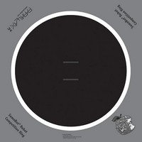
27404 Parallax Inc, 27404 Datasheet - Page 100

27404
Manufacturer Part Number
27404
Description
COMPETITION RING FOR SUMOBOT
Manufacturer
Parallax Inc
Datasheet
1.27404.pdf
(266 pages)
Specifications of 27404
Accessory Type
Hobby and Education
Product
Microcontroller Accessories
Lead Free Status / RoHS Status
Contains lead / RoHS non-compliant
For Use With/related Products
SumoBot®
Lead Free Status / RoHS Status
Lead free / RoHS Compliant, Contains lead / RoHS non-compliant
- Current page: 100 of 266
- Download datasheet (6Mb)
Figure 3-8 Front Left and Right QTI Schematics
Each QTI has four components mounted on its PCB, a 220 Ω resistor, a 470 Ω resistor, a
0.01 µF capacitor, and a QRD1114 reflective object sensor. The way these parts are
connected to the QTI's 3-pin header make it so that you can turn its power on or off by
sending either a high or low signal to its W pin. The actual sensor measurements are
taken through its R pin. For example, to turn the left QTI sensor on, send a high signal to
P10. The left QTI is controlled and monitored through P9. The SumoBot's BASIC
Stamp must set P9 high, waits 1 ms, then uses the
it takes for the voltage to drop to 1.4 V. If this time is small, the QTI senses a white
surface. If this time is long, the QTI senses a black surface.
The QRD1114 contains two components. The device inside it that controls how long the
voltage takes to drop from around 5 V to 1.4 V is called an infrared transistor. The
schematic symbol for the IR transistor is shown in Figure 3-9. While an LED is like a 1
way current valve, a transistor is more like a variable current valve. It's analogous to a
faucet. The more you turn the handle, the more water comes out. With an infrared
transistor, the more infrared light that strikes the base (B) surface, the more current (I) the
transistor allows to pass through its collector (C) and emitter (E).
RCTIME
command to measure the time
Figure 3-9
Infrared Transistor
Related parts for 27404
Image
Part Number
Description
Manufacturer
Datasheet
Request
R

Part Number:
Description:
Microcontroller Modules & Accessories DISCONTINUED BY PARALLAX
Manufacturer:
Parallax Inc

Part Number:
Description:
BOOK UNDERSTANDING SIGNALS
Manufacturer:
Parallax Inc
Datasheet:

Part Number:
Description:
TEXT INFRARED REMOTE FOR BOE-BOT
Manufacturer:
Parallax Inc
Datasheet:

Part Number:
Description:
BOARD EXPERIMENT+LCD NX-1000
Manufacturer:
Parallax Inc
Datasheet:

Part Number:
Description:
CONTROLLER 16SERVO MOTOR CONTROL
Manufacturer:
Parallax Inc
Datasheet:

Part Number:
Description:
BASIC STAMP LOGIC ANALYZER
Manufacturer:
Parallax Inc
Datasheet:

Part Number:
Description:
IC MCU 2K FLASH 50MHZ SO-18
Manufacturer:
Parallax Inc
Datasheet:

Part Number:
Description:
IC MCU 2K FLASH 50MHZ 28SSOP
Manufacturer:
Parallax Inc
Datasheet:


