DLP-2232M-G DLP Design Inc, DLP-2232M-G Datasheet - Page 18
DLP-2232M-G
Manufacturer Part Number
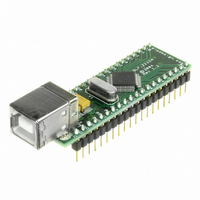
DLP-2232M-G
Description
MODULE USB ADAPTER FOR FT2232D
Manufacturer
DLP Design Inc
Datasheet
1.DLP-2232M-G.pdf
(33 pages)
Specifications of DLP-2232M-G
Main Purpose
Interface, USB 2.0 to UART (RS232) Bridge
Embedded
No
Utilized Ic / Part
FT2232D
Primary Attributes
Full Speed USB to High-Speed UART
Secondary Attributes
Royalty-Free Drivers, 2K EEPROM
Interface Type
USB
Data Bus Width
8 bit
Operating Supply Voltage
4.35 V to 5.25 V
Product
Interface Modules
For Use With/related Products
FT2232D
Lead Free Status / RoHS Status
Lead free / RoHS Compliant
Lead Free Status / RoHS Status
Lead free / RoHS Compliant, Lead free / RoHS Compliant
Other names
813-1000


thus allowing them to be connected to a 3.3V microcontroller or other external logic. It is
also possible to have one IO interface channel driving out at 5V level, and the other at
3.3V level. In this case one of the VCCIOx pins would be connected to 5V, and the other
connected to 3.3V.
A USB self-powered design uses its own power supplies, and does not draw any of its
power from the USB bus. In such cases, no special care need be taken to meet the USB
suspend current (0.5 mA) as the device does not get it’s power from the USB port.
Note that if the SI/WUx pins are not being used they should be pulled up to the same
supply as their respective VCCIOx pin.
9.0 Signal Descriptions By IO Mode and Interface Channel Configurations
9.1 232 UART Interface Mode Signal Descriptions and Interface
Configurations
When either Channel A or Channel B are in 232 UART mode the IO signal lines are
configured as follows:
Channel A
40
39
38
37
36
35
34
33
*Note 9 :
Reset and USB Suspend mode. These can be programmed to gently pull low during USB
suspend (PWREN# = “1”) by setting this option in the EEPROM.
Rev 1.6 (May 2009)
Pin#
These pins are pulled to up VCCIO via 200K resistors in the FT2232D during
Channel B
13
12
11
10
9
8
7
6
Signal
TXD
RXD
RTS#
CTS#
DTR#
DSR#
DCD#
RI#
Type
OUTPUT
INPUT
OUTPUT
INPUT
OUTPUT
INPUT
INPUT
INPUT
Description
Transmit Asynchronous Data Output
Receive Asynchronous Data Input
Request To Send Control Output / Handshake signal
Clear To Send Control Input / Handshake signal
9
Data Terminal Ready Control Output / Handshake
signal
9
Data Carrier Detect Control Input
Ring Indicator Control Input. When the Remote Wake
up option is enabled in the EEPROM, taking RI# low
can be used to resume the PC USB Host controller
from suspend.
Data Set Ready Control Input / Handshake signal
18
DLP-2232M-G DLP Design, Inc.
*Note 9
*Note 9
*Note 9
*Note
*Note
Related parts for DLP-2232M-G
Image
Part Number
Description
Manufacturer
Datasheet
Request
R

Part Number:
Description:
MODULE USB-TO-TTL PARL FIFO CONV
Manufacturer:
DLP Design Inc
Datasheet:

Part Number:
Description:
KIT DEV DLP LIGHTCOMANDER
Manufacturer:
Logic
Datasheet:

Part Number:
Description:
MODULE DATA-ACQUISITION 8-CH
Manufacturer:
DLP Design Inc
Datasheet:

Part Number:
Description:
MODULE DATA-ACQUISITION 20-CH
Manufacturer:
DLP Design Inc
Datasheet:

Part Number:
Description:
RFID READER/WRITER SNGL-CH OEM
Manufacturer:
DLP Design Inc
Datasheet:

Part Number:
Description:
Interface Modules & Development Tools DLP-245PL PACKAGED w/CCS Compiler
Manufacturer:
DLP Design Inc

Part Number:
Description:
Interface Modules & Development Tools DLP-245PB-G BOARD + CCS Compiler
Manufacturer:
DLP Design Inc
Datasheet:

Part Number:
Description:
Interface Modules & Development Tools DLP-TILT SENSOR ACCEL VIBRATION
Manufacturer:
DLP Design Inc

Part Number:
Description:
MODULE USB-MCU FT245RL W/16F877A
Manufacturer:
DLP Design Inc
Datasheet:

Part Number:
Description:
MODULE USB-TO-FPGA TRAINING TOOL
Manufacturer:
DLP Design Inc
Datasheet:

Part Number:
Description:
MODULE USB-MCU FT232R W/18F2410
Manufacturer:
DLP Design Inc
Datasheet:

Part Number:
Description:
MODULE USB-MCU FT245RL W/SX48
Manufacturer:
DLP Design Inc
Datasheet:

Part Number:
Description:
MODULE USB-MCU FT2232D W/16F877A
Manufacturer:
DLP Design Inc
Datasheet:

Part Number:
Description:
MODULE USB-TO-FPGA SPARTAN3
Manufacturer:
DLP Design Inc
Datasheet:

Part Number:
Description:
MOD USB-MCU FT245RL W/18LF8722
Manufacturer:
DLP Design Inc
Datasheet: