DLP-2232M-G DLP Design Inc, DLP-2232M-G Datasheet - Page 26
DLP-2232M-G
Manufacturer Part Number
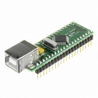
DLP-2232M-G
Description
MODULE USB ADAPTER FOR FT2232D
Manufacturer
DLP Design Inc
Datasheet
1.DLP-2232M-G.pdf
(33 pages)
Specifications of DLP-2232M-G
Main Purpose
Interface, USB 2.0 to UART (RS232) Bridge
Embedded
No
Utilized Ic / Part
FT2232D
Primary Attributes
Full Speed USB to High-Speed UART
Secondary Attributes
Royalty-Free Drivers, 2K EEPROM
Interface Type
USB
Data Bus Width
8 bit
Operating Supply Voltage
4.35 V to 5.25 V
Product
Interface Modules
For Use With/related Products
FT2232D
Lead Free Status / RoHS Status
Lead free / RoHS Compliant
Lead Free Status / RoHS Status
Lead free / RoHS Compliant, Lead free / RoHS Compliant
Other names
813-1000


When MCU Host Bus Emulation mode is enabled the IO signal lines on both channels
work together and the pins are configured as follows:
Pin# Signal
40
39
38
37
36
35
34
33
32
31
30
29
13
12
11
10
9
8
7
6
5
4
3
2
1
*Note:
application note.
Rev 1.6 (May 2009)
AD0
AD1
AD2
AD3
AD4
AD5
AD6
AD7
I/O0
I/O1
IORDY# INPUT
OSC
A8
A9
A10
A11
A12
A13
A14
A15
CS#
ALE
RD#
WR#
NC
These instructions are fully described in a separate FTDI, MPSSE mode
Type
I/O
I/O
I/O
I/O
I/O
I/O
I/O
I/O
OUTPUT Shows the clock signal that the circuit is using.
OUTPUT Extended Address Bus Bit 8
OUTPUT Extended Address Bus Bit 9
OUTPUT Extended Address Bus Bit 10
OUTPUT Extended Address Bus Bit 11
OUTPUT Extended Address Bus Bit 12
OUTPUT Extended Address Bus Bit 13
OUTPUT Extended Address Bus Bit 14
OUTPUT Extended Address Bus Bit 15
OUTPUT Negative pulse to select device during Read or Write.
OUTPUT Positive pulse to latch the address.
OUTPUT Negative Read Output.
OUTPUT Negative Write Output. (Data is setup before WR# goes
Description
Address / Data Bus Bit 0
Address / Data Bus Bit 1
Address / Data Bus Bit 2
Address / Data Bus Bit 3
Address / Data Bus Bit 4
Address / Data Bus Bit 5
Address / Data Bus Bit 6
Address / Data Bus Bit 7
MPSSE mode instructions to set / clear or read the high
byte of data can be used with this pin. *Note
MPSSE mode instructions to set, clear or read the high
byte of data can be used with this pin. Additionally, this
pin has instructions that will make the controller wait until
it is high, or wait until it is low. This can be used to
connect to an IRQ pin of a peripheral chip. The
DLP2232M will wait for the interrupt, and then read the
device, and pass the answer back to the host PC. I/O1 must
be held in input mode if this option is used. *Note
Extends the time taken to perform a Read or Write
operation if pulled low. Pull up to Vcc if not being used.
low, and is held after WR# goes high)
No Connect
26
DLP-2232M-G DLP Design, Inc.
Related parts for DLP-2232M-G
Image
Part Number
Description
Manufacturer
Datasheet
Request
R

Part Number:
Description:
MODULE USB-TO-TTL PARL FIFO CONV
Manufacturer:
DLP Design Inc
Datasheet:

Part Number:
Description:
KIT DEV DLP LIGHTCOMANDER
Manufacturer:
Logic
Datasheet:

Part Number:
Description:
MODULE DATA-ACQUISITION 8-CH
Manufacturer:
DLP Design Inc
Datasheet:

Part Number:
Description:
MODULE DATA-ACQUISITION 20-CH
Manufacturer:
DLP Design Inc
Datasheet:

Part Number:
Description:
RFID READER/WRITER SNGL-CH OEM
Manufacturer:
DLP Design Inc
Datasheet:

Part Number:
Description:
Interface Modules & Development Tools DLP-245PL PACKAGED w/CCS Compiler
Manufacturer:
DLP Design Inc

Part Number:
Description:
Interface Modules & Development Tools DLP-245PB-G BOARD + CCS Compiler
Manufacturer:
DLP Design Inc
Datasheet:

Part Number:
Description:
Interface Modules & Development Tools DLP-TILT SENSOR ACCEL VIBRATION
Manufacturer:
DLP Design Inc

Part Number:
Description:
MODULE USB-MCU FT245RL W/16F877A
Manufacturer:
DLP Design Inc
Datasheet:

Part Number:
Description:
MODULE USB-TO-FPGA TRAINING TOOL
Manufacturer:
DLP Design Inc
Datasheet:

Part Number:
Description:
MODULE USB-MCU FT232R W/18F2410
Manufacturer:
DLP Design Inc
Datasheet:

Part Number:
Description:
MODULE USB-MCU FT245RL W/SX48
Manufacturer:
DLP Design Inc
Datasheet:

Part Number:
Description:
MODULE USB-MCU FT2232D W/16F877A
Manufacturer:
DLP Design Inc
Datasheet:

Part Number:
Description:
MODULE USB-TO-FPGA SPARTAN3
Manufacturer:
DLP Design Inc
Datasheet:

Part Number:
Description:
MOD USB-MCU FT245RL W/18LF8722
Manufacturer:
DLP Design Inc
Datasheet: