MCP2515DM-PCTL Microchip Technology, MCP2515DM-PCTL Datasheet - Page 33
MCP2515DM-PCTL
Manufacturer Part Number
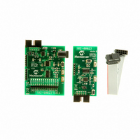
MCP2515DM-PCTL
Description
BOARD DEMO FOR MCP2515
Manufacturer
Microchip Technology
Series
PICtail™r
Type
Network Controller & Processorr
Specifications of MCP2515DM-PCTL
Main Purpose
Interface, CAN Controller
Embedded
Yes, MCU, 8-Bit
Utilized Ic / Part
MCP2515, MCP25020
Primary Attributes
Stand alone CAN Controller with CAN I/O Expander
Interface Type
CAN
Operating Voltage
5 V
Product
Modules
For Use With/related Products
MCP2515, MCP25020
Lead Free Status / RoHS Status
Contains lead / RoHS non-compliant
Secondary Attributes
-
Lead Free Status / Rohs Status
Lead free / RoHS Compliant


4.5.3
Filter matches on received messages can be
determined by the FILHIT bits in the associated
RXBnCTRL register. RXB0CTRL.FILHIT0 for buffer 0
and RXB1CTRL.FILHIT<2:0> for buffer 1.
The three FILHIT bits for receive buffer 1 (RXB1) are
coded as follows:
RXB0CTRL contains two copies of the BUKT bit and
the FILHIT<0> bit.
The coding of the BUKT bit enables these three bits to
be used similarly to the RXB1CTRL.FILHIT bits and to
distinguish a hit on filter RXF0 and RXF1 in either
RXB0 or after a roll over into RXB1.
FIGURE 4-5:
© 2010 Microchip Technology Inc.
- 101 = Acceptance Filter 5 (RXF5)
- 100 = Acceptance Filter 4 (RXF4)
- 011 = Acceptance Filter 3 (RXF3)
- 010 = Acceptance Filter 2 (RXF2)
- 001 = Acceptance Filter 1 (RXF1)
- 000 = Acceptance Filter 0 (RXF0)
Note:
- 111 = Acceptance Filter 1 (RXB1)
- 110 = Acceptance Filter 0 (RXB1)
- 001 = Acceptance Filter 1 (RXB0)
- 000 = Acceptance Filter 0 (RXB0)
RXFn
000 and 001 can only occur if the BUKT bit
in RXB0CTRL is set, allowing RXB0
messages to roll over into RXB1.
FILHIT BITS
0
Acceptance Filter Register
Message Assembly Buffer
RXFn
MESSAGE ACCEPTANCE MASK AND FILTER OPERATION
1
Identifier
RXFn
n
RXMn
0
Acceptance Mask Register
RXMn
If the BUKT bit is clear, there are six codes
corresponding to the six filters. If the BUKT bit is set,
there are six codes corresponding to the six filters, plus
two additional codes corresponding to RXF0 and RXF1
filters that roll over into RXB1.
4.5.4
If more than one acceptance filter matches, the FILHIT
bits will encode the binary value of the lowest
numbered filter that matched. For example, if filter
RXF2 and filter RXF4 match, FILHIT will be loaded with
the value for RXF2. This essentially prioritizes the
acceptance filters with a lower-numbered filter having
higher priority. Messages are compared to filters in
ascending order of filter number. This also ensures that
the message will only be received into one buffer. This
implies that RXB0 has a higher priority than RXB1.
4.5.5
The mask and filter registers can only be modified
when the MCP2515 is in Configuration mode (see
Section 10.0 “Modes of Operation”).
Note:
1
RXMn
The mask and filter registers read all '0'
when in any mode except Configuration
mode.
MULTIPLE FILTER MATCHES
CONFIGURING THE MASKS AND
FILTERS
n
MCP2515
DS21801F-page 33
RxRqst
Related parts for MCP2515DM-PCTL
Image
Part Number
Description
Manufacturer
Datasheet
Request
R

Part Number:
Description:
BOARD DAUGHTER PICTAIL MCP2515
Manufacturer:
Microchip Technology
Datasheet:

Part Number:
Description:
BOARD DEMO FOR MCP2515/51
Manufacturer:
Microchip Technology
Datasheet:

Part Number:
Description:
Manufacturer:
Microchip Technology Inc.
Datasheet:
Part Number:
Description:
Manufacturer:
Microchip Technology Inc.
Datasheet:
Part Number:
Description:
Manufacturer:
Microchip Technology Inc.
Datasheet:
Part Number:
Description:
Manufacturer:
Microchip Technology Inc.
Datasheet:
Part Number:
Description:
Manufacturer:
Microchip Technology Inc.
Datasheet:
Part Number:
Description:
Manufacturer:
Microchip Technology Inc.
Datasheet:
Part Number:
Description:
Manufacturer:
Microchip Technology Inc.
Datasheet:
Part Number:
Description:
Manufacturer:
Microchip Technology Inc.
Datasheet: