AT89STK-05 Atmel, AT89STK-05 Datasheet - Page 4
AT89STK-05
Manufacturer Part Number
AT89STK-05
Description
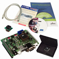
KIT STARTER FOR AT89C5131
Manufacturer
Atmel
Specifications of AT89STK-05
Main Purpose
*
Embedded
*
Utilized Ic / Part
AT89C5131
Primary Attributes
*
Secondary Attributes
*
Processor To Be Evaluated
AT89C5131A
Interface Type
RS-232, USB
Lead Free Status / RoHS Status
Contains lead / RoHS non-compliant


2.1
2.2
2.3
2.3.1
AT89C5131A Starter Kit Software User Guide
Hardware
Requirements
Software
Requirements
Default Hardware
Settings
Setting ISP Mode
The demonstration application requires the following hardware:
The following software is necessary to use the demonstration program. The software
can be found in the accompanying CD-ROM. Updated FLIP software is available on the
Atmel web site.
The AT89C5131A evaluation board must be configured as follows:
1. When BLJB is set (= 0) (default setting), the ISP mode is enabled. Plug the USB
2. When the BLJB is reset (= 1), the ISP is not set. The following procedure must
AT89C5131A evaluation board
AT89C5131A microcontroller (includes a USB bootloader)
A-B USB cable
PC running Windows
Flexible In-System Programming (FLIP) software tool
usb_hid_kbd.hex file
Power supply: from V
Quartz frequency: 16 MHz
EA jumper: Off
INT0 jumper: On
cable into the PC. The bootloader will automatically execute.
be executed.
– Press the ISP button (SW4) and plug the USB cable into your PC, or
– Press both the Reset (SW3) and ISP (SW4) buttons. First release the Reset
button and then the ISP button. The device enters ISP mode.
The user needs to re-enumerate the device using the USB Unload button
(SW1).
®
BUS
(98, Me, 2000 or XP) or Linux
through the limiter and the 3.3V regulator.
Getting Started
®
with a 1.1 or 2.0 USB Host
Section 2
Rev. 4246B–USB–11/04
2-3
Related parts for AT89STK-05
Image
Part Number
Description
Manufacturer
Datasheet
Request
R

Part Number:
Description:
KIT EVAL APPL MASS STORAGE
Manufacturer:
Atmel
Datasheet:

Part Number:
Description:
KIT DEMOBOARD 8051 MCU W/CAN
Manufacturer:
Atmel
Datasheet:

Part Number:
Description:
KIT STARTER FOR AT83C24
Manufacturer:
Atmel
Datasheet:

Part Number:
Description:
EVAL BOARD FOR AT83C26
Manufacturer:
Atmel
Datasheet:

Part Number:
Description:
KIT STARTER FOR MCU AT8XC5122/23
Manufacturer:
Atmel
Datasheet:

Part Number:
Description:
KIT STARTER FOR AT89C51RX2
Manufacturer:
Atmel
Datasheet:


Part Number:
Description:
8-Bit Microcontroller with 4K Bytes Flash
Manufacturer:
ATMEL Corporation
Datasheet:

Part Number:
Description:
DEV KIT FOR AVR/AVR32
Manufacturer:
Atmel
Datasheet:
Part Number:
Description:
INTERVAL AND WIPE/WASH WIPER CONTROL IC WITH DELAY
Manufacturer:
ATMEL Corporation
Datasheet:
Part Number:
Description:
Low-Voltage Voice-Switched IC for Hands-Free Operation
Manufacturer:
ATMEL Corporation
Datasheet:
Part Number:
Description:
MONOLITHIC INTEGRATED FEATUREPHONE CIRCUIT
Manufacturer:
ATMEL Corporation
Datasheet:
Part Number:
Description:
AM-FM Receiver IC U4255BM-M
Manufacturer:
ATMEL Corporation
Datasheet:
Part Number:
Description:
Monolithic Integrated Feature Phone Circuit
Manufacturer:
ATMEL Corporation
Datasheet: