EVB90308 Melexis Inc, EVB90308 Datasheet - Page 11
EVB90308
Manufacturer Part Number
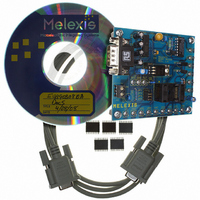
EVB90308
Description
DEMO KIT MLX90308 SENS INTERFACE
Manufacturer
Melexis Inc
Specifications of EVB90308
Rohs Status
RoHS non-compliant
Main Purpose
Interface, Sensor to ADC Interface, Programmable
Embedded
Yes, MCU, 8-Bit
Utilized Ic / Part
MLX90308
Primary Attributes
MCU Controlled Signal Conditioning for Bridge-Type Sensors
Secondary Attributes
GUI, Output Types: Absolute Voltage, Ratiometric Voltage, Current Output Mode
Other names
DK90308
DK90308
DK90308


Different Modes
Analog Mode
The parameters OF and GN represent, respectively,
offset correction and span control, while OFTCi and
GNTCi
(thermal zero shift and thermal span shift). After reset,
the firmware continuously calculates the offset and
gain DAC settings as follows: The EEPROM holds
parameters GN, OF, OFTCi and GNTCi, where “i” is
the gap number and can be 1 < i < 4. The transfer
function is described below.
Vout
{Vin+DAC_OFFSET+CSOF}
Iout = FG * DAC_GAIN * CSGN[1:0] *
{Vin+DAC_OFFSET+CSOF} * 8.85mA/V
FG = Hardware Gain (~20V/V). Part of the hardware
CSGN = Course Gain, part of byte 2 in EEPROM.
CSOF = Coarse Offset, part of byte 2 in
GAIN
DAC_GAIN (new value) ~ GN[9:0] + [GNTCi * dT]
GN[9:0] = Fixed Gain, bytes 3 and 17 in EEPROM.
GNTCi = Gain TC for a given temperature
dT = Temp. change within the appropriate gap.
How to calculate gain in the first temp. gap?:
DAC_GAIN = GN[9:0] - GNTC1 * (T1 – Temp_f1)
How to calculate gain in the other temp. gaps?:
2nd gap: DAC_GAIN = GN[9:0] + GNTC2 *
3th gap: DAC_GAIN = DAC_GAIN2 + GNTC3 *
4th gap: DAC_GAIN = DAC_GAIN3 + GNTC4 *
Where:
Temp_f = Filtered temp. (previously described).
If GNTC1 > 2047 => DAC_GAIN
If GNTC2,3,4 > 2047 => DAC_GAIN
[V/V]
MLX902xx Name of Sensor Rev Y.X 22/Aug/98
3901090308
Rev 006
(Temp_f2 – T1)
(Temp_f3 – T2)
(Temp_f4 – T3)
EEPROM.
(
. 0
design, and not changeable.
segment I. GNTCiL and GNTCiH in
EEPROM table.
97
=
represent
. 0
48
FG
* )
GN
*
1023
[
: 9
their
DAC_GAIN
] 0
. 0
temperature
48
DAC
*
CSGN[2:0]
_
GAIN
coefficients
Page 11
Page 11
*
OFFSET
DAC_OFFSET (new value) ~ OF[9:0]+[OFTCi* dT]
OF[9:0] = Fixed Gain, bytes 4 and 17 in EEPROM.
OFTCi = Offset for a given temperature
dT = Temp. change within the appropriate gap.
Calculation of the offset for a given temperature seg-
ment is performed the same way as for the gain.
Mode
The MLX90308 firmware provides the capability of
digitally processing the sensor signal in addition to the
analog processing. This capability allows for signal
correction.
Signal Correction
While in digital mode the firmware can perform signal
correction. This is an adjustment to the output level
based
coefficients can be set for five different signal ranges.
The output is obtained by the following formula:
1st gap: Output = (Signal ) * PC1 + Poff
Where:
Signal = input signal measurement;
Poff = Pressure ordinate = P1
PC1 = programmed coefficient first gap.
Following gaps:
Gap i: Output = (Signal – Pi) * PCi + Poff_i
Where
Signal = input signal measurement;
Poff_i = Pressure ordinate (i = 2,3,4,5)
Pi = Pressure signal point (i = 2,3,4,5)
PCi = programmed coefficient first gap (i = 2,3,4,5).
The PCi coefficients are coded on 12 bits: one bit for
the sign, one for the unity, and the rest for the
decimals. The Pi are coded on 10 bits (0-3FFh) in
high-low order.
PNB_TNB: contains the number of signal points,
coded on the four MSB’s. The four LSB’s are reserved
for the number of temperature points. See Table 4 and
Table 5.
7 (
Programmable Sensor Interface
segment I. OFTCiL and OFTCiH in
EEPROM table.
6
* )
on
OF
1023
[
: 9
the
] 0
6
input
DAC
signal
_
OFFSET
MLX90308
level.
Digital
[mV/V]
Adjustment
Apr/04
Related parts for EVB90308
Image
Part Number
Description
Manufacturer
Datasheet
Request
R

Part Number:
Description:
BOARD EVAL FOR USB2514/USB2514I
Manufacturer:
SMSC
Datasheet:

Part Number:
Description:
EVALUATION BOARD FOR USB3311C
Manufacturer:
SMSC
Datasheet:
Part Number:
Description:
EVALUATION BOARD FOR USB3317C
Manufacturer:
SMSC
Datasheet:

Part Number:
Description:
BOARD EVAL FOR USB2512/USB2512I
Manufacturer:
SMSC
Datasheet:

Part Number:
Description:
BOARD EVAL FOR USB2513/USB2513I
Manufacturer:
SMSC
Datasheet:
Part Number:
Description:
BOARD EVAL FOR USB2514 48-QFN
Manufacturer:
SMSC
Datasheet:

Part Number:
Description:
EVALUATION BOARD USB2241-AEZG
Manufacturer:
SMSC
Datasheet:

Part Number:
Description:
BOARD EVAL USB2524 SHARE/SWITCH
Manufacturer:
SMSC
Datasheet:

Part Number:
Description:
BOARD EVALUATION FOR USB2502
Manufacturer:
SMSC
Datasheet:
Part Number:
Description:
BOARD EVALUATION FOR USB2504
Manufacturer:
SMSC
Datasheet:

Part Number:
Description:
EVALUATION BOARD LAN9500-ABZJ
Manufacturer:
SMSC
Datasheet:
Part Number:
Description:
EVALUATION BOARD FOR LAN7500
Manufacturer:
SMSC
Datasheet:

Part Number:
Description:
EVALUATION BOARD FOR USB2412
Manufacturer:
SMSC
Datasheet: