EVB90308 Melexis Inc, EVB90308 Datasheet - Page 14
EVB90308
Manufacturer Part Number
EVB90308
Description
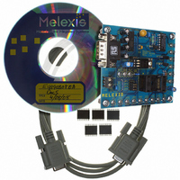
DEMO KIT MLX90308 SENS INTERFACE
Manufacturer
Melexis Inc
Specifications of EVB90308
Rohs Status
RoHS non-compliant
Main Purpose
Interface, Sensor to ADC Interface, Programmable
Embedded
Yes, MCU, 8-Bit
Utilized Ic / Part
MLX90308
Primary Attributes
MCU Controlled Signal Conditioning for Bridge-Type Sensors
Secondary Attributes
GUI, Output Types: Absolute Voltage, Ratiometric Voltage, Current Output Mode
Other names
DK90308
DK90308
DK90308


Level Steering
The level steering option allows configuration of the IO
pins as outputs to indicate the relative level of a
selected signal. See Figure 7. The levels at which the
two outputs change state are programmed by the
user. The programmed levels are set as eight bit
numbers and compared to the upper eight bits of the
digitized signal. This function utilizes the same
resources as the alarm function. The two functions
(level
simultaneously. Four bytes in the EEPROM command
this option. The first byte is used to select the input,
while the last three comprise the transition levels. The
control byte for the level steering is the same as for
the alarm. The four MSB’s hold the code for the
selected
possibilities as designated by the MUX settings (See
Table 8)
3901090308
Rev 006
Table 9. Mode Byte Bit Definition
7
6
5
4
3
2
1
0
1= EEPROM Checksum test active
0= EEPROM Checksum test inactive
0 = Analog Mode
1 = Digital Mode
0 = Alarm function inactive
1 = Alarm function active
0 = IO1/IO2 are not active outputs
1 = level steering: IO1/IO2 are active
outputs
0 = Turbo inactive
1 = Turbo active
0 = VMO inactive
1 = VMO active
0 = Internal temperature sensor active
1 = External temperature sensor
active
0 = CMO inactive
1 = CMO active
steering
Function
input.
and
The
alarm)
control
can
byte
not
has
be
several
used
EEPROM Checksum test. Checksum test failure will
force the output to the value programmed in bytes 40
and 41 of the EEPROM (See Table 10).
Digital mode must be activated when VMO and CMO
both active.
Alarm functions are like “limiting functions”:
Note: Deactivated if the level steering mode is active
Depending on the sampled input, IO1/IO2 will be a
two bit digital output. If IO1/IO2 are not active outputs,
then they will be analog inputs.
CMO has fixed digital value (EEPROM byte - see
below) if both VMO and CMO are active. To activate
this value, the digital mode must be activated.
Page 14
If defined ADC INPUT is below low alarm trigger,
If defined ADC INPUT is above high alarm trigger,
Remarks
then DIGMOD becomes active with alarm low
output).
then DIGMOD becomes active with alarm high
output.
Communications
The MLX90308 firmware transfers a complete byte of
data into and from the memory based on a simple
command structure. The commands allow data to be
read and written to and from the EEPROM and read
from the RAM. RAM data that can be read includes
the current digitized temperature and digitized GNO.
The commands are described below. Melexis provides
setup software for programming the MLX90308.
Table 8. Level Steering Bit Definitions
Programmable Sensor Interface
GNO
VMO
TPO
IAO
MLX90308
MUX Value
0010
0110
0000
0011
Apr/04
Related parts for EVB90308
Image
Part Number
Description
Manufacturer
Datasheet
Request
R

Part Number:
Description:
BOARD EVAL FOR USB2514/USB2514I
Manufacturer:
SMSC
Datasheet:

Part Number:
Description:
EVALUATION BOARD FOR USB3311C
Manufacturer:
SMSC
Datasheet:
Part Number:
Description:
EVALUATION BOARD FOR USB3317C
Manufacturer:
SMSC
Datasheet:

Part Number:
Description:
BOARD EVAL FOR USB2512/USB2512I
Manufacturer:
SMSC
Datasheet:

Part Number:
Description:
BOARD EVAL FOR USB2513/USB2513I
Manufacturer:
SMSC
Datasheet:
Part Number:
Description:
BOARD EVAL FOR USB2514 48-QFN
Manufacturer:
SMSC
Datasheet:

Part Number:
Description:
EVALUATION BOARD USB2241-AEZG
Manufacturer:
SMSC
Datasheet:

Part Number:
Description:
BOARD EVAL USB2524 SHARE/SWITCH
Manufacturer:
SMSC
Datasheet:

Part Number:
Description:
BOARD EVALUATION FOR USB2502
Manufacturer:
SMSC
Datasheet:
Part Number:
Description:
BOARD EVALUATION FOR USB2504
Manufacturer:
SMSC
Datasheet:

Part Number:
Description:
EVALUATION BOARD LAN9500-ABZJ
Manufacturer:
SMSC
Datasheet:
Part Number:
Description:
EVALUATION BOARD FOR LAN7500
Manufacturer:
SMSC
Datasheet:

Part Number:
Description:
EVALUATION BOARD FOR USB2412
Manufacturer:
SMSC
Datasheet: