IS-DEV KIT-1 NKK Switches, IS-DEV KIT-1 Datasheet - Page 13
IS-DEV KIT-1
Manufacturer Part Number
IS-DEV KIT-1
Description
SMARTSWITCH DEVELOPMENT KIT 1
Manufacturer
NKK Switches
Series
SmartSwitch™r
Datasheet
1.IS-DEV_KIT-1.pdf
(15 pages)
Specifications of IS-DEV KIT-1
Main Purpose
Switches with Programmable Display
Utilized Ic / Part
SmartSwitch™LCD Display
Primary Attributes
LCD Display Module, 2 Tact Switches, with Flash Memory
Secondary Attributes
Up to 255 Pictures and Attributes
Description/function
SMARTSWITCH Development Kit
For Use With
360-2431 - SERIAL CBL RJ11-DB9 FOR DEV KIT360-2430 - POWER SUPPLY 240VAC FOR DEV KIT360-2429 - POWER SUPPLY 120VAC FOR DEV KIT
Lead Free Status / RoHS Status
Not applicable / Not applicable
Embedded
-
Lead Free Status / Rohs Status
Lead free / RoHS Compliant
For Use With/related Products
Smart Switch - Part IS-SO108
Other names
360-2325


7850 East Gelding Drive • Scottsdale, AZ 85260-3420
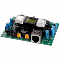
Connectors: Four
J3 Auxiliary Port:
Pin
1
3
5
7
9
This port has 7 lines of Input/output. No firmware has been written for this port. Five of these lines can be
analog. These lines are connected to the micro controller port pins.
We will add firmware upon request.
J1A
J1
J2
RS232
Adjustment:
Switches:
IS-Dev Kit-1 Users Manual A.doc
Power connector: Power Jack 2.5 mm male. Center positive.
Alternative power connector: 2 pin header .1” spacing. Pin1 GND, pin2 +9V
Communication: RJ11
POT1: LCD viewing angle/contrast adjustment.
POT2: Beeper volume adjustment.
This controller has 1 socket for the display. The JB switches are soldered.
1
Toll Free 1.877.2BUYNKK (877.228.9655) • Phone 480.991.0942 • Fax 480.998.1435
10x1 header .1”x.1” spacing.
Function
GND
AN3
AN1
RB7
RB6
2
GND
www.nkkswitches.com • Email engineering@nkkswitches.com
3
TX
IS-Dev Kit-1 Users Manual
Pin
2
4
6
8
10
4
RX
5
GND
6
Function
AN4
AN2
AN0
GND
GND
Page 13 of 15
0110
Related parts for IS-DEV KIT-1
Image
Part Number
Description
Manufacturer
Datasheet
Request
R

Part Number:
Description:
SMARTSWITCH DEVELOPMENT KIT 5C
Manufacturer:
NKK Switches
Datasheet:

Part Number:
Description:
KIT DEV FOR LCD 64X32 SWITCH
Manufacturer:
NKK Switches
Datasheet:

Part Number:
Description:
KIT DEV LCD 64X32 COMPACT SWITCH
Manufacturer:
NKK Switches
Datasheet:

Part Number:
Description:
KIT DEV FOR OLED DISPLAY
Manufacturer:
NKK Switches
Datasheet:

Part Number:
Description:
KIT DEV FOR OLED SWITCH
Manufacturer:
NKK Switches
Datasheet:

Part Number:
Description:
BOARD DEV 2RGB SW FLASH & PROGR
Manufacturer:
NKK Switches
Datasheet:

Part Number:
Description:
KIT DEV FOR LCD 64X32 DISPLAY
Manufacturer:
NKK Switches
Datasheet:

Part Number:
Description:
SMARTSWITCH DEVELOPMENT KIT 2
Manufacturer:
NKK Switches
Datasheet:

Part Number:
Description:
SMARTSWITCH DEVELOPMENT KIT 5
Manufacturer:
NKK Switches
Datasheet:

Part Number:
Description:
SMARTSWITCH DEVELOPMENT KIT 8
Manufacturer:
NKK Switches
Datasheet:

Part Number:
Description:
LED Displays PROGRAMMABLE SWITCH
Manufacturer:
NKK Switches

Part Number:
Description:
ON-OFF PLATE - SERIES -EMP
Manufacturer:
NKK Switches
Datasheet:

Part Number:
Description:
WRENCH SOCKET FOR KB SERIES PB
Manufacturer:
NKK Switches
Datasheet:

Part Number:
Description:
SWITCH TOGGLE DPST 25A SLDR 5PCS
Manufacturer:
NKK Switches
Datasheet:

Part Number:
Description:
SWITCH TOGGLE DPDT 15A SLDR 5PC
Manufacturer:
NKK Switches
Datasheet: