AD9954/PCBZ Analog Devices Inc, AD9954/PCBZ Datasheet - Page 17
AD9954/PCBZ
Manufacturer Part Number
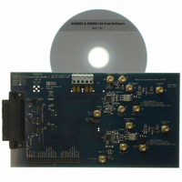
AD9954/PCBZ
Description
BOARD EVAL FOR 9954
Manufacturer
Analog Devices Inc
Series
AgileRF™r
Datasheet
1.AD9954YSVZ-REEL7.pdf
(40 pages)
Specifications of AD9954/PCBZ
Main Purpose
Timing, Direct Digital Synthesis (DDS)
Embedded
No
Utilized Ic / Part
AD9954
Primary Attributes
14-Bit DAC, 32-Bit Tuning Word Width
Secondary Attributes
400MHz, Graphical User Interface
Lead Free Status / RoHS Status
Lead free / RoHS Compliant


Upon entering this mode (via an I/O update or changing the
PS0 pin), the RAM address generator loads the RAM segment
beginning address bits of RSCW0 and the ramp rate timer loads
the RAM segment address ramp rate bits. The RAM drives data
from the beginning address, and the ramp rate timer begins
counting down to 1. When the timer reaches zero, the RAM
address is incremented if PS0 is high and decrements if PS0 is
low. Toggling the PS0 pin does not cause the device to generate
an internal I/O update; transfers of data from the I/O buffers to
the internal registers are only initiated by a rising edge on the
I/O UPDATE pin.
RAM address control is now a function of the PS0 input. When
polarity of the PS0 bit is changed, the RAM address generator
increments/decrements to the next address and the ramp rate
timer is reloaded. As in the ramp-up mode, this sequence
continues until the RAM address generator has incremented/
decremented to an address equal to the final/beginning address
as long as the PS0 input remains high/low. Once the final/
beginning address is reached, the sweep stalls until the polarity
on PS0 is changed.
All data in the RAM segment control words associated with
Profile 1, Profile 2, and Profile 3 are ignored. Only the information
in the RAM segment control word for Profile 0 is used to
control the RAM.
Continuous Bidirectional Ramp Mode
Continuous bidirectional ramp mode allows the AD9954
to offer an automatic, symmetrical sweep between two
frequencies. The AD9954 is programmed for continuous
bidirectional ramp mode using the RAM enable bit (CFR1<31>)
and programming the RAM segment mode control bits of each
desired profile to 011(b). In general, this mode is identical in
control to the bidirectional ramp mode, except the ramp up and
down is automatic (no external control via the PS0 input), and
switching profiles are valid. This mode enables generation of an
automatic saw tooth sweep characteristic.
Upon entering this mode (via an I/O update or changing the
PS1 or PS0 pins), the RAM address generator loads the RAM
segment beginning address bits of the current RSCW and the
ramp rate timer loads the RAM segment address ramp rate bits.
The RAM drives data from the beginning address, and the ramp
rate timer begins counting down to 1. When the ramp rate timer
completes the countdown, the RAM address generator increments
to the next address, and the timer reloads the ramp rate bits and
continues counting down. This continues until the RAM address
generator has incremented to an address equal to the RAM
segment final address bits of the current RSCW. Upon reaching
this final address, the RAM address generator begins
decrementing each time the ramp rate timer completes a
countdown cycle until it reaches the RAM segment beginning
address. Upon reaching the beginning address, the entire
sequence repeats until a new mode is selected.
Rev. B | Page 17 of 40
Continuous Recirculation Mode
Continuous recirculation mode allows the AD9954 to offer
an automatic, continuous unidirectional sweep between two
frequencies. The AD9954 is programmed for continuous
recirculation mode using the RAM enable bit (CFR1<31>)
and programming the RAM segment mode control bits of
each desired profile to 100(b).
Upon entering this mode (via an I/O update or changing Pin
PS1 or Pin PS0), the RAM address generator loads the RAM
segment beginning address bits of the current RSCW and the
ramp rate timer loads the RAM segment address ramp rate bits.
The RAM drives data from the beginning address, and the ramp
rate timer begins to count down to 1. When the ramp rate timer
completes a cycle, the RAM address generator increments to the
next address, and the timer reloads the ramp rate bits and
continues counting down. This sequence continues until the
RAM address generator has incremented to an address equal to
the RAM segment final address bits of the current RSCW. Upon
reaching this terminal address, the RAM address generator
reloads the RAM segment beginning address bits and the
sequence repeats until a new mode is selected.
Internal Profile Control
The AD9954 offers a mode in which a composite frequency sweep
can be built with software-programmable timing control. Internal
profile control capability disengages the PS1 pin and the PS0 pin
and enables the AD9954 to take control of switching between
profiles. Modes are defined that allow continuous or single-burst
profile switches for three combinations of profile selection bits
(see Table 8). Internal profile control mode is engaged using Bits
CFR1<29:27> per Table 8. Internal profile control is only valid
when the device is operating in RAM mode. There is no internal
profile control for linear sweeping operations.
When the internal profile control mode is engaged, the RAM
segment mode control bits are ignored; the device operates all
profiles in ramp-up mode. Switching between profiles occurs
when the RAM address generator has exhausted the memory
contents for the current profile.
AD9954
Related parts for AD9954/PCBZ
Image
Part Number
Description
Manufacturer
Datasheet
Request
R

Part Number:
Description:
BOARD EVAL FOR AD9954
Manufacturer:
Analog Devices Inc
Datasheet:


Part Number:
Description:
±1.7g Dual-Axis IMEMS Accelerometer Evaluation Board
Manufacturer:
Analog Devices Inc
Datasheet:
Part Number:
Description:
Inertial Sensor Evaluation System
Manufacturer:
Analog Devices Inc
Datasheet:
Part Number:
Description:
Manufacturer:
Analog Devices Inc
Datasheet:
Part Number:
Description:
Manufacturer:
Analog Devices Inc
Datasheet:
Part Number:
Description:
Manufacturer:
Analog Devices Inc
Datasheet:
Part Number:
Description:
Manufacturer:
Analog Devices Inc
Datasheet:
Part Number:
Description:
Manufacturer:
Analog Devices Inc
Datasheet:
Part Number:
Description:
Manufacturer:
Analog Devices Inc
Datasheet:
Part Number:
Description:
Manufacturer:
Analog Devices Inc
Datasheet:
Part Number:
Description:
Manufacturer:
Analog Devices Inc
Datasheet:
Part Number:
Description:
Manufacturer:
Analog Devices Inc
Datasheet: