CDB3310 Cirrus Logic Inc, CDB3310 Datasheet - Page 14
CDB3310
Manufacturer Part Number
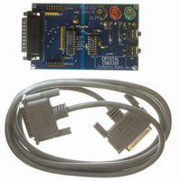
CDB3310
Description
BOARD EVAL FOR CS3310 COL CTRL
Manufacturer
Cirrus Logic Inc
Datasheet
1.CS3310-KSZ.pdf
(17 pages)
Specifications of CDB3310
Main Purpose
Audio, Volume Control
Embedded
No
Utilized Ic / Part
CS3310
Primary Attributes
Stereo Volume Control, 0.5 dB Step Size, Serial Control
Secondary Attributes
-95.5 dB Attenuation, +31.5 dB Gain, 0.001% THD+N, 116 dB Dynamic Range
Product
Audio Modules
Lead Free Status / RoHS Status
Contains lead / RoHS non-compliant
Lead Free Status / RoHS Status
Lead free / RoHS Compliant, Contains lead / RoHS non-compliant
Other names
598-1000


Analog Inputs and Outputs
AINL, AINR - Left and Right Channel Analog Inputs, Pins 16, 9.
AOUTL, AOUTR - Left and Right Channel Analog Outputs, Pins 14, 11.
Digital Pins
SDATAI - Serial Data Input, Pin 3.
SDATAO - Serial Data Output, Pin 7.
SCLK - Serial Input Clock, Pin 6.
CS - Chip Select, Pin 2.
MUTE - Mute, Pin 8.
14
Analog input connections for the left and right channels. Nominally ±3.75 volts for a full
scale input.
Analog outputs for the left and right channels. Nominally ±3.75 volts for a full scale
output.
Serial input data that sets the analog output level of the left and right channels. The
data is formatted in a 16-bit word. The first eight bits clocked into this pin control the
analog output level for the right channel, and the second eight bits clocked into the
device control the analog output level for the left channel. The data is clocked into the
CS3310 by the rising edge of SCLK.
Serial output data that provides daisy-chaining of multiple CS3310’s. This serial output
will output the previous sixteen bits of volume control data that were clocked into the
SDATAI pin. SDATAO will enter a High Impedance State when CS is High.
Serial clock that clocks in the individual bits of serial data from the SDATAI pin. This
clock is also used to clock out the individual bits from the SDATAO pin. The SDATAI
data is latched on the rising edge, and SDATAO data is clocked out on the falling
edge.
When high, the SDATAO output is held in a high impedance state. A falling transition
defines the start of the 16-bit volume control word into the device. The 16-bit input
data is latched into the control register on the rising edge of CS.
Forces both the left and right analog output channels to ground. An offset calibration is
initiated following the low transition of MUTE. Calibration requires a minimum mute
period of 2 ms.
CS3310
DS82F1
Related parts for CDB3310
Image
Part Number
Description
Manufacturer
Datasheet
Request
R

Part Number:
Description:
Development Kit
Manufacturer:
Cirrus Logic Inc
Datasheet:
Part Number:
Description:
Development Kit
Manufacturer:
Cirrus Logic Inc
Datasheet:


Part Number:
Description:
High-efficiency PFC + Fluorescent Lamp Driver Reference Design
Manufacturer:
Cirrus Logic Inc
Datasheet:
Part Number:
Description:
Development Kit
Manufacturer:
Cirrus Logic Inc
Datasheet:
Part Number:
Description:
Development Kit
Manufacturer:
Cirrus Logic Inc
Datasheet:

Part Number:
Description:
Development Kit
Manufacturer:
Cirrus Logic Inc
Datasheet:
Part Number:
Description:
Development Kit
Manufacturer:
Cirrus Logic Inc
Datasheet:
Part Number:
Description:
Development Kit
Manufacturer:
Cirrus Logic Inc
Datasheet:
Part Number:
Description:
Development Kit
Manufacturer:
Cirrus Logic Inc
Datasheet:

Part Number:
Description:
EVALUATION BOARD FOR CS8427
Manufacturer:
Cirrus Logic Inc
Datasheet:

Part Number:
Description:
BOARD EVAL FOR CS8416 RCVR
Manufacturer:
Cirrus Logic Inc
Datasheet:

Part Number:
Description:
EVALUATION BOARD FOR CS8420
Manufacturer:
Cirrus Logic Inc
Datasheet:

Part Number:
Description:
KIT DEVELOPMENT EP9315 ARM9
Manufacturer:
Cirrus Logic Inc
Datasheet:

Part Number:
Description:
KIT DEVELOPMENT EP9302 ARM9
Manufacturer:
Cirrus Logic Inc
Datasheet: