Z8FMC160100KITG Zilog, Z8FMC160100KITG Datasheet - Page 197
Z8FMC160100KITG
Manufacturer Part Number
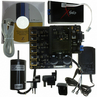
Z8FMC160100KITG
Description
KIT DEV FOR Z8 ENCORE Z8FMC16100
Manufacturer
Zilog
Series
Z8 Encore! MC™r
Datasheets
1.Z8FMC160100KIT.pdf
(7 pages)
2.Z8FMC160100KIT.pdf
(383 pages)
3.Z8FMC160100KITG.pdf
(2 pages)
4.Z8FMC160100KITG.pdf
(15 pages)
Specifications of Z8FMC160100KITG
Main Purpose
Power Management, Motor Control
Embedded
Yes, MCU, 8-Bit
Utilized Ic / Part
Z8FMC16100
Primary Attributes
3-Ph DC Motors
Secondary Attributes
Graphical User Interface
For Use With
269-4664 - KIT ACC OPTO-ISO USB SMART CABLE269-4661 - KIT ACC ETHERNET SMART CABLE269-4539 - KIT ACCESSORY USB SMART CABLE
Lead Free Status / RoHS Status
Lead free / RoHS Compliant
Other names
269-4660


PS024613-0910
I
2
C Baud Rate High and Low Byte Registers
STOP—Send Stop Condition
When set, this bit causes the I
STOP condition after the byte in the I
a byte has been received in a receive operation. When set, this bit is reset by the I
Controller after a STOP condition has been sent or by deasserting the
1, it cannot be cleared to 0 by writing to the register.
If STOP is set while a slave mode transaction is underway, the STOP bit will be cleared by
hardware.
BIRQ—Baud Rate Generator Interrupt Request
This bit is ignored when the I
Controller is disabled (
causing an interrupt to occur every time the baud rate generator counts down to one. The
baud rate generator runs continuously in this mode, generating periodic interrupts.
TXI—Enable TDRE interrupts
This bit enables interrupts when the I
NAK—Send NAK
Setting this bit sends a Not Acknowledge condition after the next byte of data has been
received. It is automatically deasserted after the Not Acknowledge is sent or the IEN bit is
cleared. If this bit is 1, it cannot be cleared to 0 by writing to the register.
FLUSH—Flush Data
Setting this bit clears the I
ing of the I
has been written to the I
FILTEN—I
Setting this bit enables low-pass digital filters on the SDA and SCL input signals. This
function provides the spike suppression filter required in I2C Fast Mode. These filters
reject any input pulse with periods less than a full system clock cycle. The filters introduce
a 3-system clock cycle latency on the inputs.
The I
combine to form a 16-bit reload value,
2
C Baud Rate High and Low Byte registers, shown in
2
C Data register when an NAK condition is received after the next data byte
2
C Signal Filter Enable
IEN
2
C Data register. Reading this bit always returns 0.
2
C Data register and sets the
= 0) the baud rate generator is used as an additional timer
2
2
C Controller is enabled. If this bit is set = 1 when the I
C Controller (when configured as the Master) to send the
2
2
C Data register is empty.
C Shift register has completed transmission or after
BRG
[15:0], for the I
I
2
C Baud Rate High and Low Byte Registers
Z8FMC16100 Series Flash MCU
TDRE
2
Table 95
C Baud Rate Generator.
bit to 1. This bit allows flush-
Product Specification
and
IEN
Table
bit. If this bit is
96,
2
C
2
C
185
Related parts for Z8FMC160100KITG
Image
Part Number
Description
Manufacturer
Datasheet
Request
R

Part Number:
Description:
Communication Controllers, ZILOG INTELLIGENT PERIPHERAL CONTROLLER (ZIP)
Manufacturer:
Zilog, Inc.
Datasheet:

Part Number:
Description:
KIT DEV FOR Z8 ENCORE 16K TO 64K
Manufacturer:
Zilog
Datasheet:

Part Number:
Description:
KIT DEV Z8 ENCORE XP 28-PIN
Manufacturer:
Zilog
Datasheet:

Part Number:
Description:
DEV KIT FOR Z8 ENCORE 8K/4K
Manufacturer:
Zilog
Datasheet:

Part Number:
Description:
KIT DEV Z8 ENCORE XP 28-PIN
Manufacturer:
Zilog
Datasheet:

Part Number:
Description:
DEV KIT FOR Z8 ENCORE 4K TO 8K
Manufacturer:
Zilog
Datasheet:
Part Number:
Description:
CMOS Z8 microcontroller. ROM 16 Kbytes, RAM 256 bytes, speed 16 MHz, 32 lines I/O, 3.0V to 5.5V
Manufacturer:
Zilog, Inc.
Datasheet:
Part Number:
Description:
Low-cost microcontroller. 512 bytes ROM, 61 bytes RAM, 8 MHz
Manufacturer:
Zilog, Inc.
Datasheet:
Part Number:
Description:
Z8 4K OTP Microcontroller
Manufacturer:
Zilog, Inc.
Datasheet:
Part Number:
Description:
CMOS SUPER8 ROMLESS MCU
Manufacturer:
Zilog, Inc.
Datasheet:
Part Number:
Description:
SL1866 CMOSZ8 OTP Microcontroller
Manufacturer:
Zilog, Inc.
Datasheet:
Part Number:
Description:
SL1866 CMOSZ8 OTP Microcontroller
Manufacturer:
Zilog, Inc.
Datasheet:
Part Number:
Description:
OTP (KB) = 1, RAM = 125, Speed = 12, I/O = 14, 8-bit Timers = 2, Comm Interfaces Other Features = Por, LV Protect, Voltage = 4.5-5.5V
Manufacturer:
Zilog, Inc.
Datasheet:
Part Number:
Description:
Manufacturer:
Zilog, Inc.
Datasheet: