DC-VIDEO-TVP5146N Altera, DC-VIDEO-TVP5146N Datasheet - Page 13
DC-VIDEO-TVP5146N
Manufacturer Part Number
DC-VIDEO-TVP5146N
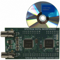
Description
VIDEO DAUGHTER CARD
Manufacturer
Altera
Series
Stratix® IIIr
Datasheets
1.EP3SL150F780C4N.pdf
(16 pages)
2.EP3SL150F780C4N.pdf
(332 pages)
3.DC-VIDEO-TVP5146N.pdf
(58 pages)
Specifications of DC-VIDEO-TVP5146N
Main Purpose
Video, Daughter Card
Embedded
No
Utilized Ic / Part
Altera Dev Kits
Primary Attributes
Dual Composite Video Input - NTSC or PAL
Secondary Attributes
10-bit BT.656 Output, Compatible with Expansion Connector, Standard on Most Altera Development Kits
Lead Free Status / RoHS Status
Lead free / RoHS Compliant
Other names
544-1704


Nonvolatile
Configuration
Altera Corporation
f
Configure the Stratix II Device Directly
You can configure the Stratix II device directly, without turning off power,
using the Quartus
1.
2.
3.
4.
5.
After successful configuration, the CONF_DONE LED (LED5)
illuminates.
Refer to Quartus II Help for instructions on how to use the USB Blaster
cable.
The designer must reconfigure the Stratix II device each time power is
applied to the Stratix II DSP development board. For designers who want
to power up the board and have a design immediately present in the
Stratix II device, the board has a nonvolatile configuration scheme. This
scheme consists of flash memory and a configuration controller (U10),
which is an Altera EPM7256 PLD. The configuration controller device is
non-volatile (i.e., it does not lose its configuration data when the board is
powered down) and it comes factory-programmed with logic that
configures the Stratix II EP2S180F1020C3 device (U18) from data stored in
flash (U17) on power-up. Upon power-up, the configuration controller
begins reading data from the flash memory. The flash memory, Stratix II
device, and configuration controller are connected so that data from the
flash configures the Stratix II device in fast passive-parallel mode.
Factory & User Configurations
The configuration controller can manage two separate Stratix II device
configurations stored in flash memory: one user design and a factory
design. On power-up, the configuration controller reads one of two (user
or factory) designs from the flash memory and programs the Stratix II
device accordingly. The user can select with which design the Stratix II
device is programmed by setting the DIP switches on SW2.
Attach the cable to J21, also labeled “JTAG Stratix II”.
Open a Quartus II SRAM Object File (.sof), which starts the
Quartus II Programmer.
Select USB Blaster as the hardware.
Set the mode to JTAG.
Click Start.
Stratix II EP2S180 DSP Development Board Reference Manual
®
II software and the USB Blaster cable, as follows.
Core Version a.b.c variable
Board Components & Interfaces
2–5
Related parts for DC-VIDEO-TVP5146N
Image
Part Number
Description
Manufacturer
Datasheet
Request
R

Part Number:
Description:
CYCLONE II STARTER KIT EP2C20N
Manufacturer:
Altera
Datasheet:


Part Number:
Description:
CPLD, EP610 Family, ECMOS Process, 300 Gates, 16 Macro Cells, 16 Reg., 16 User I/Os, 5V Supply, 35 Speed Grade, 24DIP
Manufacturer:
Altera Corporation
Datasheet:
Part Number:
Description:
CPLD, EP610 Family, ECMOS Process, 300 Gates, 16 Macro Cells, 16 Reg., 16 User I/Os, 5V Supply, 15 Speed Grade, 24DIP
Manufacturer:
Altera Corporation
Datasheet:
Part Number:
Description:
Manufacturer:
Altera Corporation
Datasheet:
Part Number:
Description:
CPLD, EP610 Family, ECMOS Process, 300 Gates, 16 Macro Cells, 16 Reg., 16 User I/Os, 5V Supply, 30 Speed Grade, 24DIP
Manufacturer:
Altera Corporation
Datasheet:
Part Number:
Description:
High-performance, low-power erasable programmable logic devices with 8 macrocells, 10ns
Manufacturer:
Altera Corporation
Datasheet:
Part Number:
Description:
High-performance, low-power erasable programmable logic devices with 8 macrocells, 7ns
Manufacturer:
Altera Corporation
Datasheet:
Part Number:
Description:
Classic EPLD
Manufacturer:
Altera Corporation
Datasheet:
Part Number:
Description:
High-performance, low-power erasable programmable logic devices with 8 macrocells, 10ns
Manufacturer:
Altera Corporation
Datasheet:
Part Number:
Description:
Manufacturer:
Altera Corporation
Datasheet:
Part Number:
Description:
Manufacturer:
Altera Corporation
Datasheet:
Part Number:
Description:
Manufacturer:
Altera Corporation
Datasheet:
Part Number:
Description:
CPLD, EP610 Family, ECMOS Process, 300 Gates, 16 Macro Cells, 16 Reg., 16 User I/Os, 5V Supply, 25 Speed Grade, 24DIP
Manufacturer:
Altera Corporation
Datasheet: