DEMOBOARD TLE 6214L Infineon Technologies, DEMOBOARD TLE 6214L Datasheet - Page 7
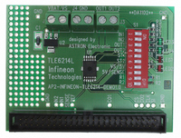
DEMOBOARD TLE 6214L
Manufacturer Part Number
DEMOBOARD TLE 6214L
Description
BOARD DEMO FOR TLE 6214L
Manufacturer
Infineon Technologies
Datasheet
1.TLE6214L.pdf
(22 pages)
Specifications of DEMOBOARD TLE 6214L
Main Purpose
Power Management, Low Side Driver (Internal FET)
Embedded
No
Utilized Ic / Part
TLE6214
Primary Attributes
2 Channel Internal Switch
Secondary Attributes
Overvoltage, Short-Circuit & Thermal Protection
Lead Free Status / RoHS Status
Lead free / RoHS Compliant
Other names
DEMOBOARDTLE6214LIN


Pin description:
the on/off register are reseted and the current consumption drastically reduced. A wake up is done by
sending a wake up command by SPI. A specified time (t
tional. The configuraton register (exception channel on/off register) values are not influenced by the
sleep mode. After wake up the outputs are Off, except the outputs are controlled by parallel inputs.
Overload Protection: The IC can be programmed to react in different ways to overload.
Current limit 1: In this mode the IC active limits the current to the specified “Current Limit 1”. If the cur-
rent limitation is active for longer than the fault filtering time this fault is reported and stored in the Fault
register.
Current limit 2: If this current limit is active for more than the specified “Overload switch off delay time”
the affected channel is turned off and the fault is reported and stored in the fault register. To turn on the
channel again this overload latch has to be reset before with an L! H transition of the input signal
(parallel /SPI depending on the programmed operation).
The two operation modes can be changed during operation of the channel.
OUTPUT 1,2 – Drain pins of the two channels. Output pins and connected to the load.
GND – Ground pins.
IN 1,2 – Parallel Input Pins of the two channels
IS / Fault / ST1 –Configurable output pin. Depending on the configuration (done by SPI command) it
has three basic functions:
VS – Logic Supply pin. Used to supply the integrated circuitry.
CS – Chip Select of the SPI (low active)
SO / ST2 – Configurable output pin. Depending on the configuration (done by SPI command) it has two
functions:
SI – Signal Input of the Serial Peripheral Interface. The pin has an internal pull down structure.
SCKL – Clock Input of the Serial Peripheral Interface. The pin has an internal pull down structure
V3.0
a) General Fault pin. This is a general fault pin (open drain) which shows a high to low transi-
b) Sense Function. In this configuration the analog output signal represents the value of the
c) Status Output for channel 1: The Status output shows the same level as the input signal of
a) Signal Output of the Serial Peripheral Interface
b) Status Output for channel 2: The Status output shows the same level as the input signal of
channel 1 as long as there is no error and the inverted input signal when any kind of error
occurs at channel 1
channel 2 as long as there is no error and the inverted input signal when any kind of error
occurs at channel 2
tion as soon as an error is latched into the diagnosis register. When the diagnosis register is
cleared this flag is also reset (high state). This fault indication can be used to generate a µC
interrupt.
load current:
Sense Current proportional load current channel 1
Sense Current proportional load current channel 2
Sense Current proportional load current of both channels (I
Page
7
wake
) after this command the IC is fully func-
Datasheet TLE 6214 L
D1
+ I
18.10.2004
D2
)
Related parts for DEMOBOARD TLE 6214L
Image
Part Number
Description
Manufacturer
Datasheet
Request
R

Part Number:
Description:
BOARD DEMO FOR TLE6208-3G
Manufacturer:
Infineon Technologies
Datasheet:

Part Number:
Description:
BOARD DEMO TLE8201R V1.0
Manufacturer:
Infineon Technologies
Datasheet:

Part Number:
Description:
BOARD DEMO FOR TLE6208-6G
Manufacturer:
Infineon Technologies
Datasheet:

Part Number:
Description:
BOARD DEMO FOR TLE 6288R
Manufacturer:
Infineon Technologies
Datasheet:

Part Number:
Description:
BOARD DEMO FOR TLE 7209-2R
Manufacturer:
Infineon Technologies
Datasheet:

Part Number:
Description:
BOARD DEMO PROFET V2.0BTS
Manufacturer:
Infineon Technologies
Datasheet:

Part Number:
Description:
BOARD DEMO FOR TLE 6244X
Manufacturer:
Infineon Technologies
Datasheet:

Part Number:
Description:
BOARD DEMO FOR TLE 6365 REV.4
Manufacturer:
Infineon Technologies
Datasheet:

Part Number:
Description:
BOARD DEMO FOR TLE 6389-2GV
Manufacturer:
Infineon Technologies
Datasheet:

Part Number:
Description:
BOARD DEMO FOR TLE 6389-2 GV50
Manufacturer:
Infineon Technologies
Datasheet:

Part Number:
Description:
Manufacturer:
Infineon Technologies AG
Datasheet:
Part Number:
Description:
Manufacturer:
Infineon Technologies AG
Datasheet:
Part Number:
Description:
Manufacturer:
Infineon Technologies AG
Datasheet:
Part Number:
Description:
Manufacturer:
Infineon Technologies AG
Datasheet:
Part Number:
Description:
Manufacturer:
Infineon Technologies AG
Datasheet: