MCP2150DM Microchip Technology, MCP2150DM Datasheet - Page 63
MCP2150DM
Manufacturer Part Number
MCP2150DM
Description
BOARD DEMO FOR MCP2150
Manufacturer
Microchip Technology
Specifications of MCP2150DM
Main Purpose
Interface, IrDA
Embedded
Yes, MCU, 8-Bit
Utilized Ic / Part
MCP2150
Primary Attributes
IrDA Controller with PIC18F MCU
Secondary Attributes
USB Interface
Processor To Be Evaluated
MCP2150, MCP2155
Processor Series
MCP215x
Interface Type
USB
Lead Free Status / RoHS Status
Lead free / RoHS Compliant
Lead Free Status / RoHS Status
Lead free / RoHS Compliant, Lead free / RoHS Compliant


FIGURE F-1:
SYSTEM HARDWARE REQUIREMENTS
© 2009 Microchip Technology Inc.
Qty
—
1
1
1
Monitor
MPLAB
Program Window
PC with one USB port
ICD2, ICD3, or Real ICE To program the MCP2150 Developer’s Board PIC18F65J50 device.
RJ-11 to ICSP Adapter
(AC164110)
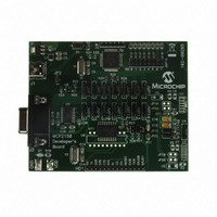
MCP2150 Developer’s
Board
Side View
¬
Appendix F. Programming the MCP2150DM
Hardware
The user may reprogram the PIC18F65J50 with their application firmware or the
supplied demo firmware.
The Programming will require the following items
• 1 PC USB port for programming
• 1 MPLAB ICD 2 module (with USB cable)
• 1 RJ-11 to ICSP Adapter (AC164110)
• CD with .HEX file to program into device (00265.HEX)
Figure F-1 shows a high level block diagram for programming the MCP2150
Developer’s Board. How to program is described in the appropriate MPLAB-IDE and
MPLAB-ICD2 documentation.
PROGRAMMING BLOCK DIAGRAM
Note:
The MCP2150DM is shipped with the default demonstration firmware
programmed into the PIC18F65J50.
PC
Purpose
To run MPLAB-IDE and communicate to the ICD or ICE hardware.
Converts RJ-11 connector of ICD 2 to pins to use for programming the
PICkit interface on the MCP2150 Developer’s Board.
The board to program.
MCP2150 DEVELOPER’S BOARD
USB Cable
MCP2150 Developer’s Board
ICD 2
USER’S GUIDE
1
RJ-11 to ICSP Cable
DS51869A-page 63
1
Related parts for MCP2150DM
Image
Part Number
Description
Manufacturer
Datasheet
Request
R

Part Number:
Description:
Manufacturer:
Microchip Technology Inc.
Datasheet:
Part Number:
Description:
Manufacturer:
Microchip Technology Inc.
Datasheet:
Part Number:
Description:
Manufacturer:
Microchip Technology Inc.
Datasheet:
Part Number:
Description:
Manufacturer:
Microchip Technology Inc.
Datasheet:
Part Number:
Description:
Manufacturer:
Microchip Technology Inc.
Datasheet:
Part Number:
Description:
Manufacturer:
Microchip Technology Inc.
Datasheet:
Part Number:
Description:
Manufacturer:
Microchip Technology Inc.
Datasheet:
Part Number:
Description:
Manufacturer:
Microchip Technology Inc.
Datasheet: