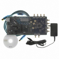
AD9520-1/PCBZ Analog Devices Inc, AD9520-1/PCBZ Datasheet - Page 10

AD9520-1/PCBZ
Manufacturer Part Number
AD9520-1/PCBZ
Description
BOARD EVAL FOR AD9520-1
Manufacturer
Analog Devices Inc
Specifications of AD9520-1/PCBZ
Design Resources
Synchronizing Multiple AD9910 1 GSPS Direct Digital Synthesizers (CN0121) Phase Coherent FSK Modulator (CN0186)
Main Purpose
Timing, Clock Generator
Embedded
No
Utilized Ic / Part
AD9520-1
Primary Attributes
12 LVPECL/24 CMOS Output Clock Generator with 2.5 GHz VCO
Secondary Attributes
SPI and I2C Compatible Control Port
Silicon Manufacturer
Analog Devices
Application Sub Type
PLL Clock Synthesizer
Kit Application Type
Clock & Timing
Silicon Core Number
AD9520-0, AD9520-2, AD9520-2
Silicon Family Name
AD9520-X
Rohs Compliant
Yes
Lead Free Status / RoHS Status
Lead free / RoHS Compliant
UG-076
FEEDBACK (N) DIVIDER WINDOW
The N Divider window shown in Figure 14 is accessed by
clicking the N DIVIDER box. It allows you to set the feedback
divider. If this box is colored gray, the PLL is off. To turn the
PLL on, click the PLL MODE box at the top of the main
window and select Norm Op.
The various modes of the N divider are described in detail in
the AD9520 data sheet. For most applications, the 8/9 or 16/17
dual modulus modes are used. For applications requiring a
divider value larger than 131119, the 32/33 mode is provided.
Different applications require different settings, and you can
experiment with the different settings.
The evaluation software has internal checking to ensure that
invalid settings are not programmed. For example, the B
counter must always be larger than the A counter. Another
restriction is that 8/9 dual modulus mode cannot be used for
VCO frequencies greater than 2400 MHz. In cases where a
feedback divider restriction cannot be resolved, you may need
to adjust the R (reference) divider to allow a different feedback
divider value. For example, it is not possible to use the internal
VCO, and a feedback divider of 30. However, the R divider can
be doubled, which allows a feedback divider of 60.
The feedback divider window has a check box for holding the N
divider in reset. When the N divider is held in reset, the PLL is
open. Therefore, this feature is seldom used.
Figure 14. Reference Divider Window
Rev. 0 | Page 10 of 16
R AND N DELAY WINDOW
The N delay window shown in Figure 15 is accessed by clicking
the N DELAY box on the main window. The R DELAY box is
identical to the N DELAY box. These delay settings, which are
most often used in zero delay mode, allow you to vary the static
phase offset of the PLL.
PHASE FREQUENCY DETECTOR (PFD) WINDOW
The Phase Frequency Detector (PFD) window shown in
Figure 16 is accessed by clicking the PFD box on the main screen.
The features accessible in this window are described in detail in
the AD9520 data sheet. The most commonly used settings are
Anti-Backlash Pulse Width and Lock Detect Counter.
For phase detector frequencies greater than 50 MHz, the PLL
may work better with the 1.3 ns antibacklash pulse width
setting.
Setting the Lock Detect Counter to values greater than 5 PFD
cycles can be useful in applications where the loop bandwidth is
low and the lock detect counter chatters during acquisition.
Figure 16. Phase Frequency Detector Window
Evaluation Board User Guide
Figure 15. N Delay Window


