AD9520-1/PCBZ Analog Devices Inc, AD9520-1/PCBZ Datasheet - Page 13
AD9520-1/PCBZ
Manufacturer Part Number
AD9520-1/PCBZ
Description
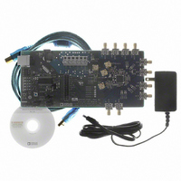
BOARD EVAL FOR AD9520-1
Manufacturer
Analog Devices Inc
Specifications of AD9520-1/PCBZ
Design Resources
Synchronizing Multiple AD9910 1 GSPS Direct Digital Synthesizers (CN0121) Phase Coherent FSK Modulator (CN0186)
Main Purpose
Timing, Clock Generator
Embedded
No
Utilized Ic / Part
AD9520-1
Primary Attributes
12 LVPECL/24 CMOS Output Clock Generator with 2.5 GHz VCO
Secondary Attributes
SPI and I2C Compatible Control Port
Silicon Manufacturer
Analog Devices
Application Sub Type
PLL Clock Synthesizer
Kit Application Type
Clock & Timing
Silicon Core Number
AD9520-0, AD9520-2, AD9520-2
Silicon Family Name
AD9520-X
Rohs Compliant
Yes
Lead Free Status / RoHS Status
Lead free / RoHS Compliant


Evaluation Board User Guide
EVALUATION SOFTWARE MENU ITEMS
MENU BAR
File Menu
The file menu has the following options:
Load Setup
Selecting Load Setup loads a previously saved AD9520 setup file
(.stp). A setup file is a text file that contains the AD9520 register
setup file, plus any evaluation board settings. Note that you
must still perform a VCO calibration.
Save Setup
Selecting Save Setup saves an AD9520 setup file (.stp). A setup
file is a text file that contains the AD9520 register setup file,
plus any evaluation board settings.
Generate Binary File
Select this menu option to generate binary setup files that can
be used by EEPROM programmers.
Exit
Exits the evaluation software. No checking is performed to
ensure that the existing setup is saved.
I/O Menu
The I/O menu includes the following options:
Select Evaluation Board
The AD9520 evaluation system allows one PC to control
multiple evaluation boards. This window allows you to select
which evaluation board the software is controlling. Click
Refresh List to detect a recently connected evaluation board
(see Figure 25).
Figure 25. Select USB Device Window
Rev. 0 | Page 13 of 16
Figure 24. Menu Bar
Configure Serial Port
The I/O Interface window allows you to control how the USB
controller interacts with the AD9520 serial port (see Figure 26).
If you are using I
which address to use. Note that it should correspond to the S5
and S6 jumper settings on the evaluation board. You can also
click Detect Current Configuration to discover which I
address is active (see Figure 26).
However, if you are attempting to program an AD9520 on a
remote board via a header cable from Connector P1, then the
I
address of the remote AD9520 that you are is attempting to
program.
View Menu
The View menu includes the following options:
Debug
This window (see Figure 23) allows you to write and read
registers directly, as well as force the various configuration pins
high and low.
Options
This window allows you to select Windows® XP visual styles.
Operational Modes Menu
This menu allows you to select any of the three operational
modes in the AD9520 data sheet.
Help Menu
Selecting Help opens the About AD9520 window, which
contains information such as revision number, region
information, and contact information.
2
C address of the on-board AD9520 must not match the I
2
C mode, this window allows you to select
Figure 26. I/O Interface Window
UG-076
2
C
2
C
Related parts for AD9520-1/PCBZ
Image
Part Number
Description
Manufacturer
Datasheet
Request
R

Part Number:
Description:
12/24 Channel Clock Gen 2,0GH
Manufacturer:
Analog Devices Inc
Datasheet:

Part Number:
Description:
12/24 Channel Clock Gen 2,0GH
Manufacturer:
Analog Devices Inc
Datasheet:
Part Number:
Description:
12/24 Channel Clock Gen 2,0GH
Manufacturer:
Analog Devices Inc
Datasheet:
Part Number:
Description:
12/24 Channel Clock Gen 2,0GH
Manufacturer:
Analog Devices Inc
Datasheet:
Part Number:
Description:
12/24 Channel Clock Gen 2,0GH
Manufacturer:
Analog Devices Inc
Datasheet:
Part Number:
Description:
Clock IC With 2.8GHz On-chip VCO
Manufacturer:
Analog Devices Inc
Datasheet:
Part Number:
Description:
Lock IC With 2.8GHz On-chip VCO
Manufacturer:
Analog Devices Inc
Datasheet:
Part Number:
Description:
12/24 Channel Clock Gen 2,5 GHz VCO
Manufacturer:
Analog Devices Inc
Datasheet:
Part Number:
Description:
12/24 Channel Clock Distribution W/ On-C
Manufacturer:
Analog Devices Inc
Datasheet:
Part Number:
Description:
12/24 Channel Clock Gen 2,25GH
Manufacturer:
Analog Devices Inc
Datasheet:
Part Number:
Description:
12/24 Channel Clock Distribution W/ On-C
Manufacturer:
Analog Devices Inc
Datasheet:
Part Number:
Description:
12/24 Channel Clock Distribution W/ On-C
Manufacturer:
Analog Devices Inc
Datasheet:
Part Number:
Description:
Clock IC With 1.6GHz On-chip VCO
Manufacturer:
Analog Devices Inc
Datasheet:
Part Number:
Description:
Clock IC With 1.6GHz On-chip VCO
Manufacturer:
Analog Devices Inc
Datasheet:
Part Number:
Description:
12/24-Output Clock Generator
Manufacturer:
Analog Devices Inc
Datasheet: