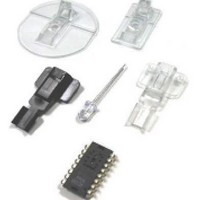
ADNK-5033-FS27 Avago Technologies US Inc., ADNK-5033-FS27 Datasheet - Page 11

ADNK-5033-FS27
Manufacturer Part Number
ADNK-5033-FS27
Description
KIT REF DES OPT MOUSE ADNS-5030
Manufacturer
Avago Technologies US Inc.
Datasheets
1.ADNK-5033-FS27.pdf
(24 pages)
2.ADNK-5033-FS27.pdf
(6 pages)
3.ADNK-5033-FS27.pdf
(32 pages)
Specifications of ADNK-5033-FS27
Main Purpose
Reference Design, Optical Mouse
Utilized Ic / Part
ADNS-5030
Wireless Frequency
27 MHz
Interface Type
USB
Modulation
FSK
For Use With/related Products
MC68HC908QY4A, MC68HC908JB12
Lead Free Status / RoHS Status
Lead free / RoHS Compliant
Secondary Attributes
-
Embedded
-
Primary Attributes
-
Lead Free Status / Rohs Status
Lead free / RoHS Compliant
MC68HC908JB12 Receiver Firmware
The MC68HC908JB12 receiver firmware is compiled
under CASM08Z.EXE from P&E Microcomputer Inc. The
firmware includes the following files:
MOTSTART.asm
Program entry point after power up or reset. Constant
and Variable definition, I/O and timer initialization
routines are contained in this files.
USB-MAIN.asm
USB main program. USB endpoints transmit setting,
Suspend and Resume handler are included.
HID-KBD.ASM
USB Standard Device Request Handler and HID Class
Device Requester handler.
KBD-MSE.H
Header file containing the USB HID device descriptors.
JB16-INT.ASM
USB Interrupt Service Routines. USB control transfer
handler.
RX_T1.ASM
Timer 1 Interrupt service routine. It contains the capture
routine for receiving and decoding the incoming RF
mouse packet.
RX_T2.ASM
Timer 2 Interrupt service routine. Timer Capture routine
can be added here for addition RF channel receiving,
e.g. a keyboard channel.
JB12-EQ2.H
MC68HC908JB12 registers header file.
EE_FLASH.ASM
Flash erase/write routines to be used for update mouse
ID.
KEY-USB.ASM
Key maps and routines used in keyboard reference
portion.
KEYMAPTX.ASM
Routines used in Keyboard reference portion.
MACR08.ASM
MACRO library for HC08 CPU.
MC68HC908JB12 Receiver Firmware Structure
The firmware consists of three main parts:
• Main routine
• Timer interrupt routine to capture and decode
11
mouse data
• USB interrupt routine
The USB routine includes reference codes for both
universal serial bus (USB) mouse and keyboard. Thus,
it can be a reference on how to implement a composite
USB
MC68HC908JB12.
Figure 9 shows the flow of the main program for the
MC68HC908JB12 receiver. The main routine continually
checks to see if there is any valid mouse data in the
receiver buffer queue. If there is new data received,
the data will be converted to USB report format and
sent to the host via USB endpoints.
Figure 10 shows the USB interrupt routines. The USB
engine automatically responds to a valid
USB token with ACK, NAK, or STALL, depending on the
register settings, and ignore it if it’s invalid. The
firmware has to set the registers for the USB engine to
give correct response to the token in different stages.
The USB interrupt will be executed whenever there is
an EOP, resume signal from host, valid data received,
or data transmitted. The USB interrupt routine also
makes preparation for the next USB transaction and
handles any valid command or data received.
Figure 11, Figure 12 and Figure 13 show the routines
handling control transfers. Control transfers have two
or three transaction stages: setup, data (optional), and
status as shown below:
• Control write: SETUP, OUT, OUT, OUT…IN
• Control read: SETUP, IN, IN, IN…OUT
• No Data control: SETUP, IN
The firmware first distinguishes the kind of control
transfer and then does the corresponding preparation
for the next stage.
One timer interrupt routine is used to capture the RF
mouse data. The firmware flow is shown in Figure 14.
The timer is set to input capture mode. With interrupt
happens on falling and rising edge, it can calculate the
pulse width of the RF data. The routines will proceed
to detect data only if the pulse width matches the data
structure of the RF packet. The detected data bit will
be put into a temporary buffer. The timer interrupt
events will keep accruing until one complete RF packet
has been received. All the received data will then be
put into receiver buffer queue for the main program
to process. In case when USB bus is being suspended,
a received mouse packet means the USB bus and the
host computer needed to wakeup. The routine will then
signal the main routine to wakeup the host instead of
updating the receiver buffer queue. The mechanism
for the wakeup mechanism is described in more details
in the “Wakeup Detection Mechanism” section.
keyboard-mouse
device
using
the


