CDB4271 Cirrus Logic Inc, CDB4271 Datasheet - Page 11
CDB4271
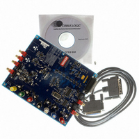
Manufacturer Part Number
CDB4271
Description
EVAL BOARD CS4271 STEREO CODEC
Manufacturer
Cirrus Logic Inc
Datasheet
1.CDB4271.pdf
(28 pages)
Specifications of CDB4271
Main Purpose
Audio, CODEC
Embedded
Yes, FPGA / CPLD
Utilized Ic / Part
CS4271
Primary Attributes
Stereo, 24-Bit, 192 kHz Sample Rate
Secondary Attributes
I²S, S/PDIF Inputs and Outputs, Analog Inputs and Outputs, GUI
Product
Audio Modules
Lead Free Status / RoHS Status
Contains lead / RoHS non-compliant
Lead Free Status / RoHS Status
Lead free / RoHS Compliant, Contains lead / RoHS non-compliant
Other names
598-1003


2. INITIAL BOARD SETUP
2.1
1) Verify that all power supplies are off before making connections.
2) Connect a +5.0 VDC power supply to the +5V (J1) red binding post. If correct configura-
3) Connect a +18.0 to +5.0 VDC power supply to the +18V (J6) green binding post. If using
4) Connect a -18.0 to -5.0 VDC power supply to the -18V (J7) yellow binding post. If using
5) Connect the common ground of the power supplies to the GND (J4) binding post.
6) Attach all required analog and digital cables to the board jacks and connectors.
7) If software control is desired, attach parallel port cable between board and PC.
8) If using the External Control Header connection, attach the required user supplied flat rib-
9) With all cables and connections in place, turn on the power supplies to the board. Turn on
10)Press and release the RESET switch S2. The LED, D5, will illuminate as long as S2 is
2.2
1) Create a directory called CDB4271 anywhere on your PC.
2) Copy CDB427X.exe from the included CD into this directory.
3) Run port95nt.exe from the CD. After running the program the system will need to
4) If desired, create a shortcut to CDB427X.exe on your desktop. You should now be able to
5) Select the LPT port you are using to connect to the CDB4271.
6) Shut down the application, reset the board, and then restart the application.
tion is other than the factory default, select VL and VD operating voltage by placing a
jumper on J8 and J9 to select either +5.0 V or +3.3 V.
the FILT position number 2 for the output filter stage, +18.0 V is required on J6.
the FILT position number 2 for the output filter stage, -18.0 V is required on J7.
bon cable to the header with the power supplies turned off.
supplies in this order: +5 V, +18 V, -18 V.
depressed indicating a reset condition. Once S2 is released, the LED should turn off. If it
remains on, an error has occurred. At this point, power off the power supplies and re-
check all connections. Apply power to the board and press and release S2. Once the LED
has turned off, the board will be setup for use.
be restarted.
run CDB427X.exe. Double-click on CDB427X.exe or its shortcut.
Power Supplies:
Installing the Software:
CDB4271
11
Related parts for CDB4271
Image
Part Number
Description
Manufacturer
Datasheet
Request
R

Part Number:
Description:
Development Kit
Manufacturer:
Cirrus Logic Inc
Datasheet:
Part Number:
Description:
Development Kit
Manufacturer:
Cirrus Logic Inc
Datasheet:


Part Number:
Description:
High-efficiency PFC + Fluorescent Lamp Driver Reference Design
Manufacturer:
Cirrus Logic Inc
Datasheet:
Part Number:
Description:
Development Kit
Manufacturer:
Cirrus Logic Inc
Datasheet:
Part Number:
Description:
Development Kit
Manufacturer:
Cirrus Logic Inc
Datasheet:

Part Number:
Description:
Development Kit
Manufacturer:
Cirrus Logic Inc
Datasheet:
Part Number:
Description:
Development Kit
Manufacturer:
Cirrus Logic Inc
Datasheet:
Part Number:
Description:
Development Kit
Manufacturer:
Cirrus Logic Inc
Datasheet:
Part Number:
Description:
Development Kit
Manufacturer:
Cirrus Logic Inc
Datasheet:

Part Number:
Description:
EVALUATION BOARD FOR CS8427
Manufacturer:
Cirrus Logic Inc
Datasheet:

Part Number:
Description:
BOARD EVAL FOR CS8416 RCVR
Manufacturer:
Cirrus Logic Inc
Datasheet:

Part Number:
Description:
EVALUATION BOARD FOR CS8420
Manufacturer:
Cirrus Logic Inc
Datasheet:

Part Number:
Description:
KIT DEVELOPMENT EP9315 ARM9
Manufacturer:
Cirrus Logic Inc
Datasheet:

Part Number:
Description:
KIT DEVELOPMENT EP9302 ARM9
Manufacturer:
Cirrus Logic Inc
Datasheet: