CDB4271 Cirrus Logic Inc, CDB4271 Datasheet - Page 6
CDB4271
Manufacturer Part Number
CDB4271
Description
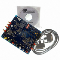
EVAL BOARD CS4271 STEREO CODEC
Manufacturer
Cirrus Logic Inc
Datasheet
1.CDB4271.pdf
(28 pages)
Specifications of CDB4271
Main Purpose
Audio, CODEC
Embedded
Yes, FPGA / CPLD
Utilized Ic / Part
CS4271
Primary Attributes
Stereo, 24-Bit, 192 kHz Sample Rate
Secondary Attributes
I²S, S/PDIF Inputs and Outputs, Analog Inputs and Outputs, GUI
Product
Audio Modules
Lead Free Status / RoHS Status
Contains lead / RoHS non-compliant
Lead Free Status / RoHS Status
Lead free / RoHS Compliant, Contains lead / RoHS non-compliant
Other names
598-1003


6
The resistor designated by R2 (see Figure 1) can be adjusted to change the gain of the in-
strumentation amp. The feedback resistors ‘R’ on the two sides of the instrumentation amp
must be equal.
A resistor divider pad (parallel combination of R5 // R8 // R10 and R22 for AOUTR) has been
placed after the low pass filter to bring the circuit back to unity gain (selectable with jumper
J15 for AOUTR).
In the resistor divider pad, three 3.92 k , 1/4 W, 1210 size resistors are used in parallel to
provide a combined resistance of 1.30 k and a combined power handling of 3/4 W. This is
done to provide sufficient power handling capability to accommodate the high signal levels
output from the instrumentation amplifier stage. When not using the instrumentation amplifi-
er, these resistors may be reduced to a single 1.30 k , 1/10 W, 0805 size resistor (for muting
attenuation purposes).
In certain places throughout the output circuit, 1/8 W, 1206 size and 1/4 W, 1210 size resis-
tors are used. Similar to the parallel resistors in the resistor divider pad, these are used to
provide sufficient power handling capability in order to accommodate the high signal levels
output from the instrumentation amplifier stage. When not using the instrumentation amplifi-
er, these resistors may all be replaced with 1/10 W, 0805 size resistors.
The attenuation provided by the output mute transistor (Q2 for AOUTR) is determined by the
resistor-divider formed between the collector-emitter on-resistance and the output resistance
of the LPF (R5 // R8 // R10 for AOUTR). The greater the output resistance, the greater the
attenuation will be for a given transistor. The trade off is that a high output impedance is not
usually desirable, and may affect the voltage transfer to the next stage based upon its input
impedance.
The same resistance that affects the transistor mute level also affects the HPF formed with
the output DC-block capacitor (C26 for AOUTR). For LPF configuration 2, the values for the
DC-block capacitor and output resistor pad (R5 // R8 // R10 and R22 for AOUTR) were cho-
sen to minimize the rise in distortion performance at low frequency due to the electrolytic's
Figure 1. Instrumentation Amplifier Configuration
In+
In-
R
2
+
+
-
-
R
R
Out+
Out-
CDB4271
Related parts for CDB4271
Image
Part Number
Description
Manufacturer
Datasheet
Request
R

Part Number:
Description:
Development Kit
Manufacturer:
Cirrus Logic Inc
Datasheet:
Part Number:
Description:
Development Kit
Manufacturer:
Cirrus Logic Inc
Datasheet:


Part Number:
Description:
High-efficiency PFC + Fluorescent Lamp Driver Reference Design
Manufacturer:
Cirrus Logic Inc
Datasheet:
Part Number:
Description:
Development Kit
Manufacturer:
Cirrus Logic Inc
Datasheet:
Part Number:
Description:
Development Kit
Manufacturer:
Cirrus Logic Inc
Datasheet:

Part Number:
Description:
Development Kit
Manufacturer:
Cirrus Logic Inc
Datasheet:
Part Number:
Description:
Development Kit
Manufacturer:
Cirrus Logic Inc
Datasheet:
Part Number:
Description:
Development Kit
Manufacturer:
Cirrus Logic Inc
Datasheet:
Part Number:
Description:
Development Kit
Manufacturer:
Cirrus Logic Inc
Datasheet:

Part Number:
Description:
EVALUATION BOARD FOR CS8427
Manufacturer:
Cirrus Logic Inc
Datasheet:

Part Number:
Description:
BOARD EVAL FOR CS8416 RCVR
Manufacturer:
Cirrus Logic Inc
Datasheet:

Part Number:
Description:
EVALUATION BOARD FOR CS8420
Manufacturer:
Cirrus Logic Inc
Datasheet:

Part Number:
Description:
KIT DEVELOPMENT EP9315 ARM9
Manufacturer:
Cirrus Logic Inc
Datasheet:

Part Number:
Description:
KIT DEVELOPMENT EP9302 ARM9
Manufacturer:
Cirrus Logic Inc
Datasheet: