CDB4265 Cirrus Logic Inc, CDB4265 Datasheet - Page 40
CDB4265
Manufacturer Part Number
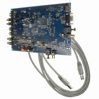
CDB4265
Description
BOARD EVAL FOR CS4265 CODEC
Manufacturer
Cirrus Logic Inc
Specifications of CDB4265
Main Purpose
Audio, CODEC
Embedded
No
Utilized Ic / Part
CS4265
Primary Attributes
Stereo, 24-Bit, 192 kHz Sample Rate
Secondary Attributes
Graphic User Interface, S/PDIF/ I2S / I2C / SPI Interface
Description/function
Audio CODECs
Operating Supply Voltage
5 V
Product
Audio Modules
For Use With/related Products
CS4265
Lead Free Status / RoHS Status
Contains lead / RoHS non-compliant
Lead Free Status / RoHS Status
Lead free / RoHS Compliant, Contains lead / RoHS non-compliant
Other names
598-1001


40
6.9
6.9.1
6.9.2
6.10
Reserved
7
ADC Input Control - Address 09h
DAC Channel A Volume Control - Address 0Ah
See
PGA Soft Ramp or Zero Cross Enable (Bits 4:3)
Function:
Soft Ramp Enable
Soft Ramp allows level changes, both muting and attenuation, to be implemented by incrementally ramp-
ing, in 1/8 dB steps, from the current level to the new level at a rate of 1 dB per 8 left/right clock periods.
See
Zero Cross Enable
Zero Cross Enable dictates that signal-level changes, either by attenuation changes or muting, will occur
on a signal zero crossing to minimize audible artifacts. The requested level change will occur after a time-
out period between 512 and 1024 sample periods (10.7 ms to 21.3 ms at 48 kHz sample rate) if the signal
does not encounter a zero crossing. The zero cross function is independently monitored and implemented
for each channel. See
Soft Ramp and Zero Cross Enable
Soft Ramp and Zero Cross Enable dictate that signal-level changes, either by attenuation changes or mut-
ing, will occur in 1/8 dB steps and be implemented on a signal zero crossing. The 1/8 dB level change will
occur after a time-out period between 512 and 1024 sample periods (10.7 ms to 21.3 ms at 48 kHz sam-
ple rate) if the signal does not encounter a zero crossing. The zero cross function is independently mon-
itored and implemented for each channel. See
Analog Input Selection
Function:
These bits are used to select the input source for the PGA and ADC. Please see
6.11 DAC Channel B Volume Control - Address
Table
PGASoft
Reserved
0
0
1
1
6
13.
Table 13. PGA Soft Cross or Zero Cross Mode Selection
Reserved
Select
PGAZeroCross
Table
0
1
5
13.
0
1
0
1
(Bit 0)
Table 14. Analog Input Selection
PGASoft
4
Changes to affect immediately
Zero Cross enabled
Soft Ramp enabled
Soft Ramp and Zero Cross enabled (default)
Microphone-Level Input
Table
PGA/ADC Input
Line-Level Input
PGAZero
0Bh.
13.
3
Reserved
Mode
2
Reserved
Table
1
14.
CS4265
Select
DS657F2
0
Related parts for CDB4265
Image
Part Number
Description
Manufacturer
Datasheet
Request
R

Part Number:
Description:
Development Kit
Manufacturer:
Cirrus Logic Inc
Datasheet:
Part Number:
Description:
Development Kit
Manufacturer:
Cirrus Logic Inc
Datasheet:


Part Number:
Description:
High-efficiency PFC + Fluorescent Lamp Driver Reference Design
Manufacturer:
Cirrus Logic Inc
Datasheet:
Part Number:
Description:
Development Kit
Manufacturer:
Cirrus Logic Inc
Datasheet:
Part Number:
Description:
Development Kit
Manufacturer:
Cirrus Logic Inc
Datasheet:

Part Number:
Description:
Development Kit
Manufacturer:
Cirrus Logic Inc
Datasheet:
Part Number:
Description:
Development Kit
Manufacturer:
Cirrus Logic Inc
Datasheet:
Part Number:
Description:
Development Kit
Manufacturer:
Cirrus Logic Inc
Datasheet:
Part Number:
Description:
Development Kit
Manufacturer:
Cirrus Logic Inc
Datasheet:

Part Number:
Description:
EVALUATION BOARD FOR CS8427
Manufacturer:
Cirrus Logic Inc
Datasheet:

Part Number:
Description:
BOARD EVAL FOR CS8416 RCVR
Manufacturer:
Cirrus Logic Inc
Datasheet:

Part Number:
Description:
EVALUATION BOARD FOR CS8420
Manufacturer:
Cirrus Logic Inc
Datasheet:

Part Number:
Description:
KIT DEVELOPMENT EP9315 ARM9
Manufacturer:
Cirrus Logic Inc
Datasheet:

Part Number:
Description:
KIT DEVELOPMENT EP9302 ARM9
Manufacturer:
Cirrus Logic Inc
Datasheet: