STEVAL-IHM021V1 STMicroelectronics, STEVAL-IHM021V1 Datasheet
STEVAL-IHM021V1
Specifications of STEVAL-IHM021V1


Related parts for STEVAL-IHM021V1


STEVAL-IHM021V1 Summary of contents
Page 1
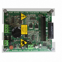
... The 100 W 3-phase inverter featuring the L6390 and STD5NK52ZD for field-oriented control (FOC) of permanent magnet synchronous motors (PMSM) demonstration board (also referred to by its order code STEVAL-IHM021V1 3-phase inverter designed to perform the FOC of sinusoidal-shaped back-EMF PMSM - with or without sensors - with nominal power up to 100 W. The device’ ...
Page 2
Contents Contents 1 Main features . . . . . . . . . . . . . . . . . . . . . . . . . . . . . . . . . . . ...
Page 3
... UM0580 9 Using the STEVAL-IHM021V1 with the STM32 FOC firmware library . 20 9.1 Environmental considerations . . . . . . . . . . . . . . . . . . . . . . . . . . . . . . . . . 20 9.2 Hardware requirements . . . . . . . . . . . . . . . . . . . . . . . . . . . . . . . . . . . . . . 21 9.3 Software requirements . . . . . . . . . . . . . . . . . . . . . . . . . . . . . . . . . . . . . . . 21 9.4 Software modifications . . . . . . . . . . . . . . . . . . . . . . . . . . . . . . . . . . . . . . . 21 10 References . . . . . . . . . . . . . . . . . . . . . . . . . . . . . . . . . . . . . . . . . . . . . . . . 22 11 Revision history . . . . . . . . . . . . . . . . . . . . . . . . . . . . . . . . . . . . . . . . . . . 23 Contents 3/24 ...
Page 4
... List of figures List of figures Figure 1. STEVAL-IHM021V1 demonstration board . . . . . . . . . . . . . . . . . . . . . . . . . . . . . . . . . . . . . . 1 Figure 2. Motor control system architecture Figure 3. L6390 block diagram . . . . . . . . . . . . . . . . . . . . . . . . . . . . . . . . . . . . . . . . . . . . . . . . . . . . . . 9 Figure 4. STD5NK52ZD Figure 5. STEVAL-IHM021V1 block diagram . . . . . . . . . . . . . . . . . . . . . . . . . . . . . . . . . . . . . . . . . . 12 Figure 6. Power supply block diagram . . . . . . . . . . . . . . . . . . . . . . . . . . . . . . . . . . . . . . . . . . . . . . . . 12 Figure 7. Inverter schematics Figure 8. Power supply schematics . . . . . . . . . . . . . . . . . . . . . . . . . . . . . . . . . . . . . . . . . . . . . . . . . . 15 Figure 9. Detailed gate driving circuit Figure 10. ...
Page 5
UM0580 1 Main features The 100 W 3-phase inverter has the following characteristics. ● Wide range input voltage ● Maximum power-up to 100 W at 230 Vac input. ● Power MOSFET STD5NK52ZD-1 (4.4 A, 520 V) ● Compatible with other ...
Page 6
... A power block that makes a power conversion from the DC bus transferring it into the motor by means of a 3-phase inverter topology ● The motor itself. The STEVAL-IHM021V1 board can drive any PMSM but the FOC itself is conceived for sinusoidal-shaped back-EMF ● A power supply block that can accept from 86 to 260 Vac input voltages and provide the appropriate levels to supply both the control block and power block devices ...
Page 7
... Intended use of the demonstration board The STEVAL-IHM021V1 demonstration board is a component designed for demonstration purposes only, and must not be used for electrical installations or machinery. Technical data and information concerning the power supply conditions are detailed in the documentation and should be strictly observed ...
Page 8
... Safety and operating instructions 3.5 Operating the demonstration board A system architecture that supplies power to the STEVAL-IHM021V1 demonstration board must be equipped with additional control and protective devices in accordance with the applicable safety requirements (for example, compliance with technical equipment and accident prevention rules). ...
Page 9
UM0580 4 L6390 characteristics 4.1 Main features ● High voltage rail up to 600 V ● dV/dt immunity ± 50 V/nsec in full temperature range ● Driver current capability: – 270-mA source – 430-mA sink ● Switching times 75/35 nsec ...
Page 10
STD5NK52ZD-1 characteristics 5 STD5NK52ZD-1 characteristics The STD5NK52ZD N-channel power MOSFET in IPAK package (520 V, 1.22 Ω, 4.4 A) Zener-protected, SuperMESH™. Figure 4. STD5NK52ZD-1 ● 520 V DSS < 1.5 Ω ● R DS(on) ● ID ...
Page 11
... Board parameters 15 V auxiliary supply range – J10 15 V bias current (typical) V mains Warning: Table 2 may cause permanent damage to the devices STEVAL-IHM021V1 Min 14.5 8 – avoid damaging the board when feeding the +15-V voltage supply through the auxiliary connector (J10), remove jumper J8 and supply the +15 V before connecting the mains ...
Page 12
... Board architecture 7 Board architecture The STEVAL-IHM021V1 can be schematized as shown in Figure 5. STEVAL-IHM021V1 block diagram 7.1 Power supply The power supply can address the AC input voltage ranging from 30 Vac up to 270 Vac. The alternate current input is rectified by a diode bridge and a bulk capacitor to generate a direct current bus voltage approximately equal to √ ...
Page 13
UM0580 7.2 Gate driving As mentioned previously, gate driving of the switches is performed through the latest L6390 family of devices. Refer to dead time insertion. A fault signal is also fed back to the J5 connector if an overcurrent ...
Page 14
Board schematics 8 Board schematics This section illustrates and provides an in-depth description of the board schematics. Figure 7. Inverter schematics 14/24 UM0580 AM01263v1 ...
Page 15
UM0580 Figure 8. Power supply schematics Board schematics AM01264v1 15/24 ...
Page 16
Board schematics 8.1 Gate driving circuit Figure 9 shows the circuit used to turn the power MOSFETs on and off. Figure 9. Detailed gate driving circuit During the turn-on phase, the power MOSFET gate capacitances are charged through 50-Ω resistors ...
Page 17
UM0580 Since the overcurrent protection acts as soon as the voltage on CP+ rises above Vref (approximately equal to 0.53 V), and given the default value of the shunt resistors (equal to 1.8/4 =0.45 Ω), it follows that the default ...
Page 18
... Brake function The STEVAL-IHM021V1 board provides a brake function that through the pull- single brake signal simultaneously turns the three low side switches ON , shorting the 3-phase load. The feature is accessed using one single small-signal bipolar transistor (Q7), whose function is to pull down the cathodes of six small signal diodes connected to each of the six ...
Page 19
UM0580 Figure 12. Brake circuit The brake signal is active high and 3.3-/5-V-compatible. Table 3. Truth table LIN x HINx Warning: SD Brake LVGx ...
Page 20
... This section describes the modifications to be applied to the " STM32 FOC firmware library v2.0 " in order for the firmware to be compatible with the STEVAL-IHM021V1. 9.1 Environmental considerations Warning: The kit is not electrically isolated from the DC input ...
Page 21
... UM0580 9.2 Hardware requirements The following items are required to run the STEVAL-IHM021V1 together with the " STM32 FOC firmware library ". ● The STEVAL-IHM021V1 board and MB525 board (STM32 evaluation board with MC connector). ● A high-voltage insulated AC power supply up to 230 Vac. ...
Page 22
... References 10 References This user manual provides information on the hardware features and use of the STEVAL-IHM021V1 demonstration board. For additional information on supporting software and tools, refer to the following: ● STD5NK52ZD-1 datasheet ● L6390 datasheet ● http://www.st.com/mcu/ web site, which is dedicated to the complete STMicroelectronics microcontroller portfolio ...
Page 23
UM0580 11 Revision history Table 4. Document revision history Date 29-Sep-2008 Revision 1 Initial release. Revision history Changes 23/24 ...
Page 24
... Information in this document is provided solely in connection with ST products. STMicroelectronics NV and its subsidiaries (“ST”) reserve the right to make changes, corrections, modifications or improvements, to this document, and the products and services described herein at any time, without notice. All ST products are sold pursuant to ST’s terms and conditions of sale. ...