SI2400URT-EVB Silicon Laboratories Inc, SI2400URT-EVB Datasheet - Page 2
SI2400URT-EVB
Manufacturer Part Number
SI2400URT-EVB
Description
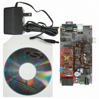
BOARD EVAL FOR SI2400 ISOMODEM
Manufacturer
Silicon Laboratories Inc
Series
ISOmodem®r
Datasheet
1.SI2400URT-EVB.pdf
(32 pages)
Specifications of SI2400URT-EVB
Main Purpose
Telecom, Modem
Embedded
No
Utilized Ic / Part
SI2400
Primary Attributes
Dual RJ-11 Connection to Phone Line, Audio Connector
Secondary Attributes
RS-232, TTL Serial & USB Interfaces
Processor To Be Evaluated
Si2400
Interface Type
RS-232, USB
Lead Free Status / RoHS Status
Contains lead / RoHS non-compliant
Lead Free Status / RoHS Status
Lead free / RoHS Compliant, Contains lead / RoHS non-compliant
Other names
336-1166


Si2400URT-EVB
1. Introduction
Notable differences between the Si2400 and other
ISOmodem products are highlighted in the bulleted list
below. For complete details and specifications, please
refer to the current Si2400 data sheet.
Unique Si2400 Features:
2
V22bis
V.22
V.21
Bell 212A
Bell 103
V.23 (1200 TX, 75 RX—Answer)
V.23 (75 TX, 1200 RX—Originate)
V.23 (600 TX, 75 RX—Answer)
V.23 (75 TX, 600 RX—Originate)
Many AT commands execute when entered without
<CR>.
AT commands must be entered in uppercase.
The +++ escape sequence is disabled at power-up
and/or reset.
S-Register address and value are entered in hex
(example: ATS0F=2B)
Result codes are abbreviated (example: “O” instead
of “OK”).
The Si2400DC power can be 3.3 V or 5 V (3.3 V
used on motherboard).
Several AT commands are required to enable the
speaker.
DTE interface default is 8N1, 2400 bps, no
handshaking, and no linefeeds with carriage returns.
ATDT is disabled if linefeeds with carriage returns
are enabled.
Some common AT Commands are not available:
Table 1. Modem Configuration Examples
ATS14=20 enables +++ escape.
ATSF4=00 removes Tx and Rx audio mute.
ATSE4=02 turns on ADC and DAC power.
ATM2 turns on speaker continuously.
ATH1
A/
ATD (must be ATDT or ATDP)
AT&Tn (use ATSE4=20 for local digital loopback)
Modulation
ATS07 =
06
02
03
00
01
14
24
10
20
Rev. 0.7
2. Si2400URT-EVB Setup and
This section explains how to set up the Si2400URT-EVB
for evaluation as an RS-232 or USB interface modem.
Jumper
connections,
settings are given. After power is applied, initial modem
setup instructions and a basic tutorial on modem
operation are provided. Si2400URT-EVB configurations
for evaluating additional features are discussed
separately.
2.1. Si2400URT-EVB Quick Start—RS-232
1. Set jumpers according to Figure 1.
2. Connect:
3. Bring up:
4. Type “AT” followed by a carriage return.
5. Type:
Command
ATSF4=00 Removes audio mute
ATSE4=02 Turns on audio ADC and DAC
ATS00=02 Auto-answer after two rings
ATS07=06 Configures modem for V.22b
ATS14=20 Enables +++ escape
Hardware flow control. Disable linefeeds with
carriage returns (linefeeds with carriage returns
disable ATDT commands).
ATM1
Evaluation
DB-9 to PC COM 1 (with a pass-through cable).
RJ-11 to phone line or test box.
the 9 V ac adaptor (or USB cable).
Turn on power to modem.
Set Terminal Program for 2400 bps 8N1.
Should echo “AT” and then an “O”.
ATS14 = 20 to enable +++ escape.
ATS07 = 06 to enable V.22b.
ATS00 = 01 for auto-answer on first ring.
Table 2. Modem Initialization Example
Interface
settings,
Turns on speaker until carrier negotiated
and
power
terminal
connection,
Function
program
configuration
PC/terminal
Related parts for SI2400URT-EVB
Image
Part Number
Description
Manufacturer
Datasheet
Request
R

Part Number:
Description:
SMD/C°/SINGLE-ENDED OUTPUT SILICON OSCILLATOR
Manufacturer:
Silicon Laboratories Inc
Part Number:
Description:
Manufacturer:
Silicon Laboratories Inc
Datasheet:
Part Number:
Description:
N/A N/A/SI4010 AES KEYFOB DEMO WITH LCD RX
Manufacturer:
Silicon Laboratories Inc
Datasheet:
Part Number:
Description:
N/A N/A/SI4010 SIMPLIFIED KEY FOB DEMO WITH LED RX
Manufacturer:
Silicon Laboratories Inc
Datasheet:
Part Number:
Description:
N/A/-40 TO 85 OC/EZLINK MODULE; F930/4432 HIGH BAND (REV E/B1)
Manufacturer:
Silicon Laboratories Inc
Part Number:
Description:
EZLink Module; F930/4432 Low Band (rev e/B1)
Manufacturer:
Silicon Laboratories Inc
Part Number:
Description:
I°/4460 10 DBM RADIO TEST CARD 434 MHZ
Manufacturer:
Silicon Laboratories Inc
Part Number:
Description:
I°/4461 14 DBM RADIO TEST CARD 868 MHZ
Manufacturer:
Silicon Laboratories Inc
Part Number:
Description:
I°/4463 20 DBM RFSWITCH RADIO TEST CARD 460 MHZ
Manufacturer:
Silicon Laboratories Inc
Part Number:
Description:
I°/4463 20 DBM RADIO TEST CARD 868 MHZ
Manufacturer:
Silicon Laboratories Inc
Part Number:
Description:
I°/4463 27 DBM RADIO TEST CARD 868 MHZ
Manufacturer:
Silicon Laboratories Inc
Part Number:
Description:
I°/4463 SKYWORKS 30 DBM RADIO TEST CARD 915 MHZ
Manufacturer:
Silicon Laboratories Inc
Part Number:
Description:
N/A N/A/-40 TO 85 OC/4463 RFMD 30 DBM RADIO TEST CARD 915 MHZ
Manufacturer:
Silicon Laboratories Inc
Part Number:
Description:
I°/4463 20 DBM RADIO TEST CARD 169 MHZ
Manufacturer:
Silicon Laboratories Inc