SI2400URT-EVB Silicon Laboratories Inc, SI2400URT-EVB Datasheet - Page 4
SI2400URT-EVB
Manufacturer Part Number
SI2400URT-EVB
Description
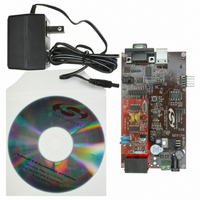
BOARD EVAL FOR SI2400 ISOMODEM
Manufacturer
Silicon Laboratories Inc
Series
ISOmodem®r
Datasheet
1.SI2400URT-EVB.pdf
(32 pages)
Specifications of SI2400URT-EVB
Main Purpose
Telecom, Modem
Embedded
No
Utilized Ic / Part
SI2400
Primary Attributes
Dual RJ-11 Connection to Phone Line, Audio Connector
Secondary Attributes
RS-232, TTL Serial & USB Interfaces
Processor To Be Evaluated
Si2400
Interface Type
RS-232, USB
Lead Free Status / RoHS Status
Contains lead / RoHS non-compliant
Lead Free Status / RoHS Status
Lead free / RoHS Compliant, Contains lead / RoHS non-compliant
Other names
336-1166


Si2400URT-EVB
2.4. Power Requirements
The Si2400URT-EVB has an onboard diode bridge,
filter capacitor, and voltage regulator. Power can be
supplied from any source capable of providing 7.5–13 V
dc or 7.5–13 V peak ac and at least 100 mA. (Additional
current may be required if a speaker is connected for
monitoring call progress tones.) Power may be applied
to the Si2400URT-EVB through the screw terminals (J3)
or the 2 mm power jack (J4). The onboard full-wave
rectifier and filter ensure that the correct polarity is
applied to the Si2400URT-EVB. Daughter card power is
supplied through voltage regulator U2 and is factory set
at 3.3 V. Power is also supplied by the USB cable and
can be used regardless of whether the modem is
configured for USB, RS-232, or direct interface mode.
Daughter card current can be measured by connecting
an ammeter between JP7 pins 1 and 2. These pins
must always be connected. Failure to connect pins 1
and 2 of JP7 through either a jumper or a low-
impedance ammeter may result in damage to the
Si2400URT-EVB.
2.5. Terminal and Line Connections
The Si2400 can be tested as a standard serial data
modem by connecting the Si2400URT-EVB to a
personal computer or other data terminal equipment
(DTE), phone line, and power. Connect a PC, RS-232,
or USB interface to the Si2400URT-EVB with the
appropriate cable. The RS-232 transceivers on the EVB
can communicate with the DTE at rates of up to 1 Mbps.
4
Figure 2. Jumper Settings—USB Interface (Outlined in Gray)
Rev. 0.7
Any standard terminal program, such as HyperTerminal
or ProComm, running on a PC can communicate with
the Si2400URT-EVB. Configure the terminal emulation
program to 2400 bps, 8 data bits, no parity, one stop bit,
and hardware flow control. Also, be sure to disable
linefeeds with carriage returns. Connect the RJ-11 jack
on the Si2400URT-EVB to an analog phone line or
telephone line simulator, such as a Teltone TLS 5.
2.6. Making Connections
With the terminal program properly configured and
running, apply power to the Si2400URT-EVB. Type
“AT<CR>”, and the modem should return “O”, indicating
the modem is working in the command mode and
communicating with the terminal. If the “O” response is
not received, try resetting the modem by pressing the
manual reset switch (S1); then type “AT<CR>” again.
Ensure that sure all commands are entered using
uppercase letters.
To take the modem off-hook, type “ATDT<CR>.” The
modem should go to the off-hook state, draw loop
current, and respond with a “t”, indicating a dial tone
detection. Typing any characters makes the modem
hang up (go on-hook) and stop drawing loop current.
To make a modem connection, type “ATDT(called
modem phone number)<CR>.” Once the connection is
established, a “c” message appears indicating the two
modems are in the data mode and communicating.
Typing on one terminal should appear on the other
terminal. To return to the command mode without
Related parts for SI2400URT-EVB
Image
Part Number
Description
Manufacturer
Datasheet
Request
R

Part Number:
Description:
SMD/C°/SINGLE-ENDED OUTPUT SILICON OSCILLATOR
Manufacturer:
Silicon Laboratories Inc
Part Number:
Description:
Manufacturer:
Silicon Laboratories Inc
Datasheet:
Part Number:
Description:
N/A N/A/SI4010 AES KEYFOB DEMO WITH LCD RX
Manufacturer:
Silicon Laboratories Inc
Datasheet:
Part Number:
Description:
N/A N/A/SI4010 SIMPLIFIED KEY FOB DEMO WITH LED RX
Manufacturer:
Silicon Laboratories Inc
Datasheet:
Part Number:
Description:
N/A/-40 TO 85 OC/EZLINK MODULE; F930/4432 HIGH BAND (REV E/B1)
Manufacturer:
Silicon Laboratories Inc
Part Number:
Description:
EZLink Module; F930/4432 Low Band (rev e/B1)
Manufacturer:
Silicon Laboratories Inc
Part Number:
Description:
I°/4460 10 DBM RADIO TEST CARD 434 MHZ
Manufacturer:
Silicon Laboratories Inc
Part Number:
Description:
I°/4461 14 DBM RADIO TEST CARD 868 MHZ
Manufacturer:
Silicon Laboratories Inc
Part Number:
Description:
I°/4463 20 DBM RFSWITCH RADIO TEST CARD 460 MHZ
Manufacturer:
Silicon Laboratories Inc
Part Number:
Description:
I°/4463 20 DBM RADIO TEST CARD 868 MHZ
Manufacturer:
Silicon Laboratories Inc
Part Number:
Description:
I°/4463 27 DBM RADIO TEST CARD 868 MHZ
Manufacturer:
Silicon Laboratories Inc
Part Number:
Description:
I°/4463 SKYWORKS 30 DBM RADIO TEST CARD 915 MHZ
Manufacturer:
Silicon Laboratories Inc
Part Number:
Description:
N/A N/A/-40 TO 85 OC/4463 RFMD 30 DBM RADIO TEST CARD 915 MHZ
Manufacturer:
Silicon Laboratories Inc
Part Number:
Description:
I°/4463 20 DBM RADIO TEST CARD 169 MHZ
Manufacturer:
Silicon Laboratories Inc