SI2400URT-EVB Silicon Laboratories Inc, SI2400URT-EVB Datasheet - Page 6
SI2400URT-EVB
Manufacturer Part Number
SI2400URT-EVB
Description
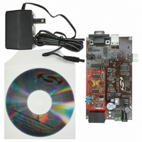
BOARD EVAL FOR SI2400 ISOMODEM
Manufacturer
Silicon Laboratories Inc
Series
ISOmodem®r
Datasheet
1.SI2400URT-EVB.pdf
(32 pages)
Specifications of SI2400URT-EVB
Main Purpose
Telecom, Modem
Embedded
No
Utilized Ic / Part
SI2400
Primary Attributes
Dual RJ-11 Connection to Phone Line, Audio Connector
Secondary Attributes
RS-232, TTL Serial & USB Interfaces
Processor To Be Evaluated
Si2400
Interface Type
RS-232, USB
Lead Free Status / RoHS Status
Contains lead / RoHS non-compliant
Lead Free Status / RoHS Status
Lead free / RoHS Compliant, Contains lead / RoHS non-compliant
Other names
336-1166


Si2400URT-EVB
connected to the DTE. Table 3 lists the interface controlled by each motherboard jumper. See Figure 7 on page 13
and Figure 17 on page 23.
3.1.6. RS-232 Interface
This operation mode uses the standard factory jumper settings illustrated in Figure 1 on page 3. The Maxim
MAX3237 transceiver interfaces directly with the TTL levels available at the serial interface of the Si2400 and,
using internal charge pumps, makes these signals compatible with the RS-232 standard. The RS-232 transceiver
on the Si2400USB-EVB can communicate at rates between 300 bps and 1 Mbps. This simplifies the connection to
PCs and other Data Terminal Equipment (DTE). The signals available on the Si2400USB-EVB serial interface
(DB9 connector) are listed in Table 4.
6
Carrier Detect
Received Data
Transmit Data
Data Terminal Ready
Signal Ground
Data Set Ready
Ready to Send
Clear to Send
Ring Indicator
Notes:
1. JP6 + JP5 jumper option.
2. JP6 Jumper option.
3. DSR connected to DTR at J1.
Jumper
JP10
JP12
JP11
JP1
JP2
JP3
JP4
JP5
JP6
JP7
JP8
JP9
J1 Name
Daughter Card Phone Line Connector.
Daughter Card Digital Connector.
Direct Access Header.
Not Used.
USB Enable (RS-232 Disable).
Options.
3.3 V Power for Daughter Card.
Disable both RS-232 and USB.
Not Used.
Not Used.
Not Used.
Enable 27 MHz Clock Option.
Table 3. Interface Selection Jumpers
Table 4. DB9 Pin Connections
J1 Symbol
RXD
DSR
TXD
DTR
RTS
CTS
CD
SG
RD
Rev. 0.7
J1 Pin
1
4
9
Function
2
3
5
6
7
8
1
2
1
Si2400 Pin
Note
14
12
nc
nc
5
6
7
3
Si2400 Name
ESC/GPIO3
GND
RXD
TXD
CTS
Related parts for SI2400URT-EVB
Image
Part Number
Description
Manufacturer
Datasheet
Request
R

Part Number:
Description:
SMD/C°/SINGLE-ENDED OUTPUT SILICON OSCILLATOR
Manufacturer:
Silicon Laboratories Inc
Part Number:
Description:
Manufacturer:
Silicon Laboratories Inc
Datasheet:
Part Number:
Description:
N/A N/A/SI4010 AES KEYFOB DEMO WITH LCD RX
Manufacturer:
Silicon Laboratories Inc
Datasheet:
Part Number:
Description:
N/A N/A/SI4010 SIMPLIFIED KEY FOB DEMO WITH LED RX
Manufacturer:
Silicon Laboratories Inc
Datasheet:
Part Number:
Description:
N/A/-40 TO 85 OC/EZLINK MODULE; F930/4432 HIGH BAND (REV E/B1)
Manufacturer:
Silicon Laboratories Inc
Part Number:
Description:
EZLink Module; F930/4432 Low Band (rev e/B1)
Manufacturer:
Silicon Laboratories Inc
Part Number:
Description:
I°/4460 10 DBM RADIO TEST CARD 434 MHZ
Manufacturer:
Silicon Laboratories Inc
Part Number:
Description:
I°/4461 14 DBM RADIO TEST CARD 868 MHZ
Manufacturer:
Silicon Laboratories Inc
Part Number:
Description:
I°/4463 20 DBM RFSWITCH RADIO TEST CARD 460 MHZ
Manufacturer:
Silicon Laboratories Inc
Part Number:
Description:
I°/4463 20 DBM RADIO TEST CARD 868 MHZ
Manufacturer:
Silicon Laboratories Inc
Part Number:
Description:
I°/4463 27 DBM RADIO TEST CARD 868 MHZ
Manufacturer:
Silicon Laboratories Inc
Part Number:
Description:
I°/4463 SKYWORKS 30 DBM RADIO TEST CARD 915 MHZ
Manufacturer:
Silicon Laboratories Inc
Part Number:
Description:
N/A N/A/-40 TO 85 OC/4463 RFMD 30 DBM RADIO TEST CARD 915 MHZ
Manufacturer:
Silicon Laboratories Inc
Part Number:
Description:
I°/4463 20 DBM RADIO TEST CARD 169 MHZ
Manufacturer:
Silicon Laboratories Inc