DEMOBOARD PROFET Infineon Technologies, DEMOBOARD PROFET Datasheet - Page 3
DEMOBOARD PROFET
Manufacturer Part Number
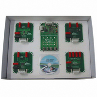
DEMOBOARD PROFET
Description
BOARD DEMO PROFET V2.0BTS
Manufacturer
Infineon Technologies
Specifications of DEMOBOARD PROFET
Main Purpose
Power Management, High Side Driver (Internal FET)
Embedded
No
Utilized Ic / Part
BTS5230, BTS5234, BTS5241, BTS6143
Primary Attributes
4 High Side Switch Boards @ 10A, 9.5A, 5.5A, 1.8A, 5 ~ 24V
Secondary Attributes
Overvoltage, Short-Circuit & Thermal Protection
Lead Free Status / RoHS Status
Lead free / RoHS Compliant
Other names
DEMOBOARDPROFETIN


1
This chapter is intended to describe a step by step procedure to get the system running
the first time. For detailed information about the hardware and software of the
PROFET Demo Kit, please refer to the “Tool Description” document.
1.1
The hardware is intended to be used the following way:
1. select one of the power boards
2. connect the control board
3. connect 12 V bulbs to the OUTx plugs of the power boards according to following
4. connect a 12 V power supply, which is able to drive the loads’ current, to the VBB and
5. check, if the jumper at the control board is placed in position “normal”
6. occasionally, the reset button has to be pressed to start-up the system after power up
7. use switches to switch on the loads
To see the performance and protection features of the device, following evaluation could
be performed:
• Open Load: Remove the load of one channel completely
• Low load: Reduce the load of one channel (e.g. P-DSO-12: Remove one 21 W bulb)
• Short Circuit to GND: Short Circuit one channel
• Reverse Polarity:
Note: Please keep in mind that short circuit evaluation as well as normal power
1)
Getting Started
table:
Power Board
P-DSO-12
P-DSO-20
P-DSO-14
Power HIC
GND plug of the power board. The control board is supplied via the power board.
The open load LED of that channel will be switched on.
The open load LED is enabled, when that channel is switched on.
The over temperature LED is enabled, when that channel is switched on.
All loads will be switched on
the control board is reverse polarity protected
dissipation will heat up the power devices. Harmful temperatures can be
reached at the device packages and the PCB!
Getting Started
Usage of Hardware
1)
Chanel 1
21 W + 21 W +
5 W
21 W
10 W
55 W
Connect the power supply in reverse polarity.
Channel 2
21 W + 21 W +
5 W
21 W
10 W
60 W
3
Channel 3
-
-
10 W
-
PROFET Demo Kit
Getting Started
Getting Started
Channel 4
-
-
10 W
-
V 2.0, 2004-04
Related parts for DEMOBOARD PROFET
Image
Part Number
Description
Manufacturer
Datasheet
Request
R

Part Number:
Description:
BOARD DEMO FOR TLE6208-3G
Manufacturer:
Infineon Technologies
Datasheet:

Part Number:
Description:
BOARD DEMO TLE8201R V1.0
Manufacturer:
Infineon Technologies
Datasheet:

Part Number:
Description:
BOARD DEMO FOR TLE6208-6G
Manufacturer:
Infineon Technologies
Datasheet:

Part Number:
Description:
BOARD DEMO FOR TLE 6288R
Manufacturer:
Infineon Technologies
Datasheet:

Part Number:
Description:
BOARD DEMO FOR TLE 6214L
Manufacturer:
Infineon Technologies
Datasheet:

Part Number:
Description:
BOARD DEMO FOR TLE 7209-2R
Manufacturer:
Infineon Technologies
Datasheet:

Part Number:
Description:
BOARD DEMO FOR TLE 6244X
Manufacturer:
Infineon Technologies
Datasheet:

Part Number:
Description:
BOARD DEMO FOR TLE 6365 REV.4
Manufacturer:
Infineon Technologies
Datasheet:

Part Number:
Description:
BOARD DEMO FOR TLE 6389-2GV
Manufacturer:
Infineon Technologies
Datasheet:

Part Number:
Description:
BOARD DEMO FOR TLE 6389-2 GV50
Manufacturer:
Infineon Technologies
Datasheet:

Part Number:
Description:
Manufacturer:
Infineon Technologies AG
Datasheet:
Part Number:
Description:
Manufacturer:
Infineon Technologies AG
Datasheet:
Part Number:
Description:
Manufacturer:
Infineon Technologies AG
Datasheet:
Part Number:
Description:
Manufacturer:
Infineon Technologies AG
Datasheet:
Part Number:
Description:
Manufacturer:
Infineon Technologies AG
Datasheet: