MCP3421EV Microchip Technology, MCP3421EV Datasheet - Page 28
MCP3421EV
Manufacturer Part Number
MCP3421EV
Description
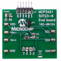
BOARD EVAL FOR MCP3421 SOT23-6
Manufacturer
Microchip Technology
Specifications of MCP3421EV
Design Resources
MCP3421EV Gerber Files
Number Of Adc's
1
Number Of Bits
18
Sampling Rate (per Second)
4
Data Interface
Serial
Inputs Per Adc
1 Single Ended
Input Range
±2.5 V
Voltage Supply Source
Single Supply
Operating Temperature
-40°C ~ 125°C
Utilized Ic / Part
MCP3421
Silicon Manufacturer
Microchip
Application Sub Type
ADC
Kit Application Type
Data Converter
Silicon Core Number
MCP3421
Kit Contents
Board
Rohs Compliant
Yes
Lead Free Status / RoHS Status
Not applicable / Not applicable
Available stocks
Company
Part Number
Manufacturer
Quantity
Price
Company:

Part Number:
MCP3421EV
Manufacturer:
Microchip Technology
Quantity:
135


MCP3421
6.1.3
The user can test the communication between the
Master (MCU) and the MCP3421 by simply checking
an acknowledge response from the MCP3421 after
sending a read or write command. Here is an example
using
FIGURE 6-3:
Test.
6.1.4
Figure 6-4
differential and single-ended inputs. Differential input
signals are connected to the V
For the single-ended input, the input signal is applied to
one of the input pins (typically connected to the V
pin) while the other input pin (typically V
grounded. All device characteristics hold for the single-
ended configuration, but this configuration loses one bit
resolution because the input can only stand in
positive half scale. Refer to Section 4.9 “Digital
Output Codes and Conversion to Real Values”.
DS22003E-page 28
SDA
SCL
a)
b)
If the device acknowledges (ACK = 0), then the
device is connected, otherwise it is not
connected.
c)
Figure
Start
Set the R/W bit “LOW” in the address byte.
Check the ACK pulse after sending the
Send a STOP bit.
address byte.
Bit
DEVICE COMMUNICATION TEST
DIFFERENTIAL AND SINGLE-
ENDED CONFIGURATION
shows typical connection examples for
6-3:
Device Code
ADC Section
1
1
2
1 0
3
I
Address Byte
2
C Bus Communications
4
1 A2 A1 A0 0
Address bits
5
IN
6
+ and V
7
8
MCP3421
Response
IN
R/W
- input pins.
9
IN
- pin) is
Stop
Bit
IN
+
FIGURE 6-4:
Ended Input Connections.
Sensor
Excitation
Excitation
(b) Single-ended Input Signal Connection:
(a) Differential Input Signal Connection:
C
C
1
2
: 0.1
: 10
R
R
µF
1
2
Input Signal
Sensor
µF
Input Signal
, Tantalum Capacitor
, Ceramic Capacitor
Differential and Single-
© 2009 Microchip Technology Inc.
V
V
V
V
IN
IN
IN
IN
+
-
+
-
MCP3421
MCP3421
V
V
DD
DD
C
C
1
1
C
C
2
2
Related parts for MCP3421EV
Image
Part Number
Description
Manufacturer
Datasheet
Request
R

Part Number:
Description:
Manufacturer:
Microchip Technology Inc.
Datasheet:
Part Number:
Description:
Manufacturer:
Microchip Technology Inc.
Datasheet:
Part Number:
Description:
Manufacturer:
Microchip Technology Inc.
Datasheet:
Part Number:
Description:
Manufacturer:
Microchip Technology Inc.
Datasheet:
Part Number:
Description:
Manufacturer:
Microchip Technology Inc.
Datasheet:
Part Number:
Description:
Manufacturer:
Microchip Technology Inc.
Datasheet:
Part Number:
Description:
Manufacturer:
Microchip Technology Inc.
Datasheet:
Part Number:
Description:
Manufacturer:
Microchip Technology Inc.
Datasheet: