KDC5514EVALZ Intersil, KDC5514EVALZ Datasheet - Page 8
KDC5514EVALZ
Manufacturer Part Number
KDC5514EVALZ
Description
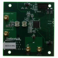
DAUGHTER CARD FOR KAD5514
Manufacturer
Intersil
Series
FemtoCharge™r
Datasheets
1.KAD5514P-25Q72.pdf
(34 pages)
2.KMB-001LEVALZ.pdf
(7 pages)
3.KDC5514EVALZ.pdf
(9 pages)
Specifications of KDC5514EVALZ
Number Of Adc's
1
Number Of Bits
14
Sampling Rate (per Second)
250M
Data Interface
Parallel
Inputs Per Adc
1 Differential
Input Range
1.47 Vpp
Power (typ) @ Conditions
429mW @ 250MSPS
Voltage Supply Source
Single Supply
Operating Temperature
-40°C ~ 85°C
Utilized Ic / Part
KAD5514P-25, KMB001 Motherboard
For Use With
KMB001LEVAL - MOTHERBOARD FOR LVDS ADC CARD
Lead Free Status / RoHS Status
Lead free / RoHS Compliant
Other names
KDC5514EVAL
KDC5514EVAL
KDC5514EVAL
Available stocks
Company
Part Number
Manufacturer
Quantity
Price
Company:

Part Number:
KDC5514EVALZ
Manufacturer:
Intersil
Quantity:
5


Switching Specifications
NOTES:
10. SPI Interface timing is directly proportional to the ADC sample period (4ns at 250Msps).
12. The CSB setup time increases in sleep mode due to the reduced power state, CSB setup time in Nap mode is equal to normal mode CSB setup
11. The SPI may operate asynchronously with respect to the ADC sample clock.
ADC OUTPUT
Aperture Delay
RMS Aperture Jitter
Output Clock to Data
Propagation Delay, LVDS Mode
(Note 9)
Output Clock to Data
Propagation Delay, CMOS Mode
(Note 9)
Latency (Pipeline Delay)
Overvoltage Recovery
SPI INTERFACE (Notes 10, 11)
SCLK Period
SCLK Duty Cycle (t
t
CSB↓ to SCLK↑ Setup Time
CSB↑ after SCLK↑ Hold Time
Data Valid to SCLK↑ Setup Time Write
Data Valid after SCLK↑ Hold
Time
Data Valid after SCLK↓ Time
Data Invalid after SCLK↑ Time
Sleep Mode CSB↓ to SCLK↑
Setup Time (Note 12)
8. The Tri-Level Inputs internal switching thresholds are approximately 0.43V and 1.34V. It is advised to float the inputs, tie to ground or AVDD
9. The input clock to output clock delay is a function of sample rate, using the output clock to latch the data simplifies data capture for most
LO
/t
depending on desired function.
applications. Contact factory for more info if needed.
time (4ns min).
CLK
)
PARAMETER
HI
/t
CLK
or
8
DDR, Rising Edge
DDR, Falling Edge
SDR, Falling Edge
DDR, Rising Edge
DDR, Falling Edge
SDR, Falling Edge
Write Operation
Read Operation
Read or Write
Read or Write
Read or Write
Write
Read
Read
Read or Write in Sleep Mode
CONDITION
KAD5514P
SYMBOL
t
t
t
t
t
t
t
DHW
DSW
t
t
t
t
t
t
OVR
DVR
DHR
CLK
CLK
DC
DC
DC
DC
DC
DC
t
j
t
t
t
L
A
H
A
S
S
-260
-160
-260
-220
-310
-310
MIN
150
16
66
25
1
3
1
3
3
TYP
375
-50
-40
-10
-90
-50
8.5
60
10
50
1
MAX
16.5
120
230
230
200
110
200
75
September 10, 2009
(Note 10)
UNITS
cycles
cycles
cycles
cycles
cycles
cycles
cycles
cycles
cycles
cycles
ps
ps
ps
ps
ps
ps
ps
µs
%
fs
FN6804.2
Related parts for KDC5514EVALZ
Image
Part Number
Description
Manufacturer
Datasheet
Request
R

Part Number:
Description:
DAUGHTER CARD FOR KAD5514
Manufacturer:
Intersil
Datasheet:

Part Number:
Description:
Intersil Corporation [CMOS Serial Controller Interface]
Manufacturer:
Intersil Corporation
Datasheet:
Part Number:
Description:
Manufacturer:
Intersil Corporation
Datasheet:
Part Number:
Description:
357-036-542-201 CARDEDGE 36POS DL .156 BLK LOPRO
Manufacturer:
Intersil Corporation
Datasheet:
Part Number:
Description:
1024-Word x 4-Bit LSI Static RAM
Manufacturer:
Intersil Corporation
Datasheet:
Part Number:
Description:
General Purpose NPN Transistor Arrays FN341.4
Manufacturer:
Intersil Corporation
Datasheet:
Part Number:
Description:
CMOS 16-Bit Microprocessor
Manufacturer:
Intersil Corporation
Datasheet:
Part Number:
Description:
Manufacturer:
Intersil Corporation
Datasheet:
Part Number:
Description:
Manufacturer:
Intersil Corporation
Datasheet:
Part Number:
Description:
Manufacturer:
Intersil Corporation
Datasheet:
Part Number:
Description:
Manufacturer:
Intersil Corporation
Datasheet:
Part Number:
Description:
CMOS 6-Bit Latch and Decoder Memory Interfaces
Manufacturer:
Intersil Corporation
Datasheet:
Part Number:
Description:
CA3046General Purpose NPN Transistor Arrays
Manufacturer:
Intersil Corporation
Datasheet:
Part Number:
Description:
Manufacturer:
Intersil Corporation
Datasheet:
Part Number:
Description:
TR909 DLC/FLC SLIC with Low Power Standby
Manufacturer:
Intersil Corporation
Datasheet: