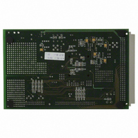
EVAL-AD7725CBZ Analog Devices Inc, EVAL-AD7725CBZ Datasheet - Page 20

EVAL-AD7725CBZ
Manufacturer Part Number
EVAL-AD7725CBZ
Description
BOARD EVALUATION FOR AD7725
Manufacturer
Analog Devices Inc
Datasheet
1.AD7725BSZ.pdf
(28 pages)
Specifications of EVAL-AD7725CBZ
Number Of Adc's
1
Number Of Bits
16
Sampling Rate (per Second)
900k
Data Interface
Serial, Parallel
Inputs Per Adc
1 Differential
Input Range
±VREF
Power (typ) @ Conditions
615mW @ 900kSPS
Voltage Supply Source
Analog and Digital
Operating Temperature
-40°C ~ 85°C
Utilized Ic / Part
AD7725
Lead Free Status / RoHS Status
Lead free / RoHS Compliant
AD7725
Filter Design
The bit stream of data from the modulator and preset filter is
available to the postprocessor at a frequency of CLKIN/8. Due
to the nature of the design of the postprocessor, there is an
unavoidable minimum decimate by 2 resulting in the maximum
output data rate of any filter being CLKIN/16.
A filter can be either FIR or IIR in design. FIR filters are inherently
stable and have linear phase. However, they are computationally
inefficient and require more coefficients for a given roll-off com-
pared to IIR filters. IIR filters have the disadvantage of being
potentially unstable and having nonlinear phase. The maximum
number of taps that the postprocessor can hold is 108. Therefore,
a single filter with 108 taps can be generated, or a multistage filter
can be designed whereby the total number of taps adds up to 108.
Design Factors
Stop-Band Attenuation and Transition Width
In filter design, it is desirable to have a large stop-band attenu-
ation and a narrow filter transition width. To achieve both of
these, a large number of filter taps is required. Therefore some
compromises have to be made during the design to be able to
optimize the amount of taps used. There is usually a trade-off of
stop-band attenuation for transition width, or vice versa. For
example, a filter with a cutoff frequency of 100 kHz that rolls off
between 100 kHz and 200 kHz uses fewer taps than a filter with a
cutoff frequency of 100 kHz that rolls off between 100 kHz and
150 kHz. To reduce the number of taps used to achieve a
certain specification, a multistage filter can be designed that
performs decimation between stages. The first filter stage can be
used to perform decimation and as a prefilter to remove out-of-
band noise, then the subsequent stages can have more stringent
specifications.
Decimation
Decimation reduces the output data rate of the filter, resulting in
lower input data rates for subsequent filter stages. When decimation
is used in a multistage filter, the noise is wrapped around f
time the bit stream is decimated by 2. It is therefore important to
appropriately filter out the quantization noise that will wrap into
the band of interest when decimation occurs, prior to decimation.
With appropriate filtering, the noise floor will increase by 3 dB each
time the data stream is decimated by 2; however the noise floor is
down at 120 dB prior to decimation. Therefore, with suitable deci-
mation, the SNR will be 83 dB typically at the AD7725 output.
Decimating the data rate allows an improvement in the filter
transition width equal to the inverse of the decimation factor.
For FIR filters, if a filter is designed for an input data rate of
half the maximum data rate, i.e., the previous filter stage had
decimation by 2, the filter can obtain half the transition width of
a filter designed for the maximum input data rate for a given
number of taps. For example, the number of taps required to
generate a filter with a cutoff frequency of 100 kHz and a
stop-band frequency of 200 kHz will equal the number of taps
required to generate a filter with a cutoff frequency of 100 kHz
S
/2 each
–20–
and a stop-band frequency of 150 kHz if the data stream is
decimated by 2 prior to the filtering stage. For IIR filters,
decimation has no effect on the transition width.
When decimation is performed, the amount of filter coefficients
required to achieve certain filter specifications is reduced, result-
ing in a reduction in the power dissipation of the device to
realize the filter. Therefore, if a one-stage filter meets the roll-off
and stop-band attenuation requirements of the application but
is dissipating more power than is acceptable, then decimation
will provide a solution here. Prior to decimating, a suggestion is
to use a half-band filter as these require a low number of taps to
accomplish simple low-pass filtering. A half-band filter has its
midpoint of the transition region centered on half the Nyquist
frequency (or f
subsequent stages is reduced, so is the bandwidth.
Figure 22 shows that for a given transition width, as the
decimation factor prior to the filter is increased the current
consumption is reduced, resulting in reduced power dissipation.
Power Consumption vs. Filter Taps vs. CLKIN Frequency
When designing filters for the AD7725, an important factor to
take into account is the power consumption. There is a direct
relationship between DI
the postprocessor, and the CLKIN frequency. The maximum
I
age is 150 mA. The more filter taps used, the higher the DI
Also, the higher the CLKIN frequency, the higher the DI
Therefore, a trade-off sometimes needs to be made between
CLKIN frequency and filter taps to stay within the power
budget of the part.
These power constraints are built into the filter design package,
Filter Wizard. As the filter is being designed, the power con-
sumption is shown and is highlighted once the power budget
has been exceeded.
DD
(combined AI
Figure 22. I
Transition Width of 66 kHz as Shown in Figure 1
120
100
80
60
40
0
S
/4). By decimating though, because the input to
DD
DD
vs. Decimation for a Filter with a
and DI
2
DD
DECIMATION FACTOR
, the number of filter taps used in
DD
) allowed by the AD7725 pack-
4
6
REV. A
8
DD
DD
.
.


