EVL6566B-65W-QR STMicroelectronics, EVL6566B-65W-QR Datasheet - Page 30
EVL6566B-65W-QR
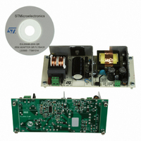
Manufacturer Part Number
EVL6566B-65W-QR
Description
BOARD EVAL SMPS FOR L6566B
Manufacturer
STMicroelectronics
Type
Power Factor Correctionr
Specifications of EVL6566B-65W-QR
Main Purpose
AC/DC, Primary Side
Outputs And Type
1, Isolated
Power - Output
65W
Voltage - Output
700V
Voltage - Input
8 ~ 23 V
Regulator Topology
Flyback
Frequency - Switching
100kHz
Board Type
Fully Populated
Utilized Ic / Part
L6566B
Input Voltage
90 V to 265 V
Output Voltage
1.8 V to 12 V
Board Size
150 mm x 75 mm
Product
Power Management Modules
Dimensions
150 mm x 75 mm
Lead Free Status / RoHS Status
Lead free by exemption / RoHS compliant by exemption
Current - Output
-
Lead Free Status / Rohs Status
Lead free / RoHS Compliant
For Use With/related Products
L6566B
Other names
497-10165


Application information
5.7
30/51
Equation 8
where Lp is the inductance of the primary winding. In case a constant maximum power
capability vs. the input voltage is not required, the VFF pin can be grounded, directly or
through a resistor (see
setpoint at 1 V, or biased at a fixed voltage through a divider from VREF to get a lower
setpoint.
It is possible to bypass the pin to ground with a small film capacitor (e.g. 1-10 nF) to ensure
a clean operation of the IC even in a noisy environment.
The pin is internally forced to ground during UVLO, after activating any latched protection
and when pin COMP is pulled below its low clamp voltage (see
block on page 26
Hiccup-mode OCP
A third comparator senses the voltage on the current sense input and shuts down the device
if the voltage on the pin exceeds 1.5 V, a level well above that of the maximum overcurrent
setpoint (1 V). Such an anomalous condition is typically generated by either a short circuit of
the secondary rectifier or a shorted secondary winding or a hard-saturated flyback
transformer.
Figure 18. Hiccup-mode OCP: timing diagram
To distinguish an actual malfunction from a disturbance (e.g. induced during ESD tests), the
first time the comparator is tripped the protection circuit enters a “warning state”. If in the
next switching cycle the comparator is not tripped, a temporary disturbance is assumed and
the protection logic will be reset in its idle state; if the comparator will be tripped again a real
malfunction is assumed and the L6566B will be stopped. Depending on the time relationship
OCP latch
Vcc_OK
(pin 5)
(pin 7)
(pin 4)
Vcc
Vcc
V
GD
Vcc
Vcc
CS
restart
OFF
ON
1.5 V
).
Section 5.11: OVP block on page 35
Secondary diode is shorted here
k
opt
=
3
Rs
Td
Lp
), hence fixing the overcurrent
Section 5.5: PWM control
L6566B
t
t
t
t
t
Related parts for EVL6566B-65W-QR
Image
Part Number
Description
Manufacturer
Datasheet
Request
R

Part Number:
Description:
BOARD EVAL FOR L6566B
Manufacturer:
STMicroelectronics
Datasheet:

Part Number:
Description:
BOARD EVAL FOR L6566B
Manufacturer:
STMicroelectronics
Datasheet:

Part Number:
Description:
BOARD EVAL FOR L6566B
Manufacturer:
STMicroelectronics
Datasheet:

Part Number:
Description:
Power Management Modules & Development Tools L6566B-60WQR Eval Board
Manufacturer:
STMicroelectronics
Part Number:
Description:
STMicroelectronics [RIPPLE-CARRY BINARY COUNTER/DIVIDERS]
Manufacturer:
STMicroelectronics
Datasheet:
Part Number:
Description:
STMicroelectronics [LIQUID-CRYSTAL DISPLAY DRIVERS]
Manufacturer:
STMicroelectronics
Datasheet:

Part Number:
Description:
BOARD EVAL FOR MEMS SENSORS
Manufacturer:
STMicroelectronics
Datasheet:
Part Number:
Description:
NPN TRANSISTOR POWER MODULE
Manufacturer:
STMicroelectronics
Datasheet:
Part Number:
Description:
TURBOSWITCH ULTRA-FAST HIGH VOLTAGE DIODE
Manufacturer:
STMicroelectronics
Datasheet:
Part Number:
Description:
Manufacturer:
STMicroelectronics
Datasheet:
Part Number:
Description:
DIODE / SCR MODULE
Manufacturer:
STMicroelectronics
Datasheet:
Part Number:
Description:
DIODE / SCR MODULE
Manufacturer:
STMicroelectronics
Datasheet: