EVL6566B-65W-QR STMicroelectronics, EVL6566B-65W-QR Datasheet - Page 33
EVL6566B-65W-QR
Manufacturer Part Number
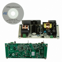
EVL6566B-65W-QR
Description
BOARD EVAL SMPS FOR L6566B
Manufacturer
STMicroelectronics
Type
Power Factor Correctionr
Specifications of EVL6566B-65W-QR
Main Purpose
AC/DC, Primary Side
Outputs And Type
1, Isolated
Power - Output
65W
Voltage - Output
700V
Voltage - Input
8 ~ 23 V
Regulator Topology
Flyback
Frequency - Switching
100kHz
Board Type
Fully Populated
Utilized Ic / Part
L6566B
Input Voltage
90 V to 265 V
Output Voltage
1.8 V to 12 V
Board Size
150 mm x 75 mm
Product
Power Management Modules
Dimensions
150 mm x 75 mm
Lead Free Status / RoHS Status
Lead free by exemption / RoHS compliant by exemption
Current - Output
-
Lead Free Status / Rohs Status
Lead free / RoHS Compliant
For Use With/related Products
L6566B
Other names
497-10165


L6566B
5.10
This function is useful to implement a latched overtemperature protection very easily by
biasing the pin with a divider from VREF, where the upper resistor is an NTC physically
located close to a heating element like the MOSFET, or the transformer. The DIS pin is a
high impedance input, thus it is prone to pick up noise, which might give origin to undesired
latch-off of the device. It is possible to bypass the pin to ground with a small film capacitor
(e.g. 1-10 nF) to prevent any malfunctioning of this kind.
Figure 20. Operation after latched disable activation: timing diagram
Soft-start and delayed latched shutdown upon overcurrent
At device start-up, a capacitor (C
charged by an internal current generator, I
clamped. During this ramp, the overcurrent setpoint progressively rises from zero to the
value imposed by the voltage on the VFF pin (15, see
latch and voltage feedforward blocks on page 27
gradually, hence controlling the start-up inrush current. The time needed for the overcurrent
setpoint to reach its steady state value, referred to as soft-start time, is approximately:
Equation 12
During the ramp (i.e. until V
are disabled.
Vcc
(pin 16)
AC_OK
Vcc
(pin 8)
(pin 5)
(pin 4)
ON
Vcc
V
Vcc
Vcc
DIS
GD
HVstart
-0.5
restart
4.5V
Vin
Vth
OFF
ON
HV generator is turned on
T
SS
SS
= 2 V) all the functions that monitor the voltage on pin COMP
=
Css
I
SS
SS
) connected between the SS pin (14) and ground is
1
V
csx
Input source is removed here
V (
SS1
VFF
, from zero up to about 2 V where it is
)
); MOSFET’s conduction time increases
=
Css
I
SS
HV generator turn-on is disabled here
1
Section 5.6: PWM comparator, PWM
⎛
⎜ ⎜
⎝
1
−
V
VFF
3
⎞
⎟ ⎟
⎠
Disable latch is reset here
Application information
Restart is quicker
33/51
t
t
t
t
t
Related parts for EVL6566B-65W-QR
Image
Part Number
Description
Manufacturer
Datasheet
Request
R

Part Number:
Description:
BOARD EVAL FOR L6566B
Manufacturer:
STMicroelectronics
Datasheet:

Part Number:
Description:
BOARD EVAL FOR L6566B
Manufacturer:
STMicroelectronics
Datasheet:

Part Number:
Description:
BOARD EVAL FOR L6566B
Manufacturer:
STMicroelectronics
Datasheet:

Part Number:
Description:
Power Management Modules & Development Tools L6566B-60WQR Eval Board
Manufacturer:
STMicroelectronics
Part Number:
Description:
STMicroelectronics [RIPPLE-CARRY BINARY COUNTER/DIVIDERS]
Manufacturer:
STMicroelectronics
Datasheet:
Part Number:
Description:
STMicroelectronics [LIQUID-CRYSTAL DISPLAY DRIVERS]
Manufacturer:
STMicroelectronics
Datasheet:

Part Number:
Description:
BOARD EVAL FOR MEMS SENSORS
Manufacturer:
STMicroelectronics
Datasheet:
Part Number:
Description:
NPN TRANSISTOR POWER MODULE
Manufacturer:
STMicroelectronics
Datasheet:
Part Number:
Description:
TURBOSWITCH ULTRA-FAST HIGH VOLTAGE DIODE
Manufacturer:
STMicroelectronics
Datasheet:
Part Number:
Description:
Manufacturer:
STMicroelectronics
Datasheet:
Part Number:
Description:
DIODE / SCR MODULE
Manufacturer:
STMicroelectronics
Datasheet:
Part Number:
Description:
DIODE / SCR MODULE
Manufacturer:
STMicroelectronics
Datasheet: