NCP3101BUCK1GEVB ON Semiconductor, NCP3101BUCK1GEVB Datasheet - Page 14
NCP3101BUCK1GEVB
Manufacturer Part Number
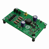
NCP3101BUCK1GEVB
Description
EVAL BOARD FOR NCP3101BUCK1G
Manufacturer
ON Semiconductor
Specifications of NCP3101BUCK1GEVB
Design Resources
NCP3101BUCK1 EVB BOM NCP3101BUCKL1GEVB Gerber Files NCP3101BUCK1 EVB Schematic
Main Purpose
DC/DC, Step Down
Outputs And Type
1, Non-Isolated
Voltage - Output
3.3V
Current - Output
6A
Voltage - Input
13.2V
Regulator Topology
Buck
Frequency - Switching
275kHz
Board Type
Fully Populated
Utilized Ic / Part
NCP3101
Lead Free Status / RoHS Status
Lead free / RoHS Compliant
Power - Output
-
Lead Free Status / Rohs Status
Lead free / RoHS Compliant
For Use With/related Products
NCP3101BUCK1G
Other names
NCP3101BUCK1GEVBOS


Co
C
F
I
ra
but tends to range from 1 nH to 20 nH, where ceramic
capacitors have the lowest inductance and electrolytic
capacitors have the highest. The calculated contributing
voltage ripple from ESL is shown for the switch on and
switch off below:
D
ESL
F
Ipp
response of the power supply. For the first few microseconds
of a load transient, the output capacitor supplies current to
the load. Once the regulator recognizes a load transient, it
adjusts the duty ratio, but the current slope is limited by the
inductor value.
drops due to the current variation inside the capacitor and the
ESR (neglecting the effect of the ESL). The user must also
consider the resistance added due to PCB traces and any
connections to the load. The additional resistance must be
added to the ESR of the output capacitor.
Co
I
OUT
TRAN
SW
SW
V
19.6 mV + 6 * 26% 12 mW )
OUT
V
15.6 mV +
V
5.92 mV +
DV
111 mV + 3 A
The ESL of capacitors depends on the technology chosen,
The output capacitor is a basic component for fast
During a load step transient, the output voltage initially
ESR
ESR
ESR_C
ESLON
ESLOFF
OUT−ESR
+ I
+
+
ESL * I
10 nH * 1.56 A * 275 kHz
10 nH * 1.56 A * 275 kHz
OUT
ESL * I
+ I
= Output capacitor ESR
= Output capacitance
= Switching frequency
= Output current
= Ripple current ratio
= Duty ratio
= Capacitor inductance
= Switching frequency
= Peak−to−peak current
= Output capacitor Equivalent Series
Resistance
= Output transient current
TRAN
* ra CO
1 * D
PP
D
12 mW ) 25mW
1 * 27.5%
PP
27.5%
* F
* F
SW
ESR
SW
CO
³
³
ESR
)
8 * 275 kHz * 820 mF
8 * F
) RCON ³
SW
1
* C
1
OUT
(eq. 14)
(eq. 15)
(eq. 16)
(eq. 17)
http://onsemi.com
14
DV
current during the load transient without discharging it. The
voltage drop due to output capacitor discharge is given by
the following equation:
C
D
I
L
VCC
V
DV
capacitor bank dominates the transient response. Please note
that DV
other, and the larger of these two voltages will determine the
maximum deviation of the output voltage (neglecting the
effect of the ESL).
of the NCP3101C demo board with the configuration shown
in Figure 27. The transient response was measured for the
load current step from 3 A to 6 A (50% to 100% load).
OS−CON, output capacitors are 2 x 100 mF ceramic and
OS−CON as mentioned in Table 5. Typical transient
response waveforms are shown in Figure 27.
at http://www.edc.sanyo.com.
TRAN
OUT
DV
4.16 mV +
OUT
MAX
OUT
A minimum capacitor value is required to sustain the
In a typical converter design, the ESR of the output
Table 5 shows values of voltage drop and recovery time
Input capacitors are 2 x 47 mF ceramic and 1 x 270 mF
More information about OS−CON capacitors is available
OUT
OUT
OUT−DIS
_
_
OUT
ESR
DIS
_
+
2 * 82% * 820 mF
DIS
2 * D
= Voltage deviation of V
= Voltage deviation of V
and DV
= Output capacitance
= Maximum duty ratio
= Output transient current
= Output inductor value
= Input voltage
= Output voltage
effects of ESR
effects of capacitor discharge
MAX
3 A
OUT_ESR
* C
I
TRAN
2
OUT
5.6 mH
2
12 V * 3.3 V
are out of phase with each
L
V
OUT
CC
* V
OUT
OUT
OUT
due to the
due to the
³
(eq. 18)
Related parts for NCP3101BUCK1GEVB
Image
Part Number
Description
Manufacturer
Datasheet
Request
R

Part Number:
Description:
Wide Input Voltage Synchronous Buck Converter
Manufacturer:
ON Semiconductor
Datasheet:
Part Number:
Description:
ON Semiconductor [VOLTAGE REGULATOR]
Manufacturer:
ON Semiconductor
Datasheet:
Part Number:
Description:
357-036-542-201 CARDEDGE 36POS DL .156 BLK LOPRO
Manufacturer:
ON Semiconductor
Datasheet:
Part Number:
Description:
357-036-542-201 CARDEDGE 36POS DL .156 BLK LOPRO
Manufacturer:
ON Semiconductor
Datasheet:
Part Number:
Description:
357-036-542-201 CARDEDGE 36POS DL .156 BLK LOPRO
Manufacturer:
ON Semiconductor
Datasheet:
Part Number:
Description:
357-036-542-201 CARDEDGE 36POS DL .156 BLK LOPRO
Manufacturer:
ON Semiconductor
Datasheet:
Part Number:
Description:
357-036-542-201 CARDEDGE 36POS DL .156 BLK LOPRO
Manufacturer:
ON Semiconductor
Datasheet:
Part Number:
Description:
357-036-542-201 CARDEDGE 36POS DL .156 BLK LOPRO
Manufacturer:
ON Semiconductor
Datasheet:
Part Number:
Description:
357-036-542-201 CARDEDGE 36POS DL .156 BLK LOPRO
Manufacturer:
ON Semiconductor
Datasheet:
Part Number:
Description:
357-036-542-201 CARDEDGE 36POS DL .156 BLK LOPRO
Manufacturer:
ON Semiconductor
Datasheet:
Part Number:
Description:
357-036-542-201 CARDEDGE 36POS DL .156 BLK LOPRO
Manufacturer:
ON Semiconductor
Datasheet:
Part Number:
Description:
357-036-542-201 CARDEDGE 36POS DL .156 BLK LOPRO
Manufacturer:
ON Semiconductor
Datasheet:
Part Number:
Description:
Manufacturer:
ON Semiconductor
Datasheet:
Part Number:
Description:
Manufacturer:
ON Semiconductor
Datasheet: