DEMOBOARD TLE 6389-2GV Infineon Technologies, DEMOBOARD TLE 6389-2GV Datasheet - Page 32
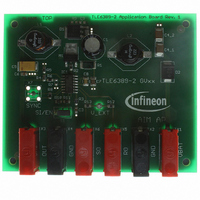
DEMOBOARD TLE 6389-2GV
Manufacturer Part Number
DEMOBOARD TLE 6389-2GV
Description
BOARD DEMO FOR TLE 6389-2GV
Manufacturer
Infineon Technologies
Datasheet
1.TLE6389-3G_V50.pdf
(38 pages)
Specifications of DEMOBOARD TLE 6389-2GV
Main Purpose
DC/DC, Step Down
Outputs And Type
1, Non-Isolated
Voltage - Output
7 ~ 15V
Current - Output
2.5A
Voltage - Input
5 ~ 60V
Regulator Topology
Buck
Frequency - Switching
360kHz
Board Type
Fully Populated
Utilized Ic / Part
TLE6389
Lead Free Status / RoHS Status
Lead free / RoHS Compliant
Power - Output
-
Other names
DEMOBOARDTLE6389-2GVIN


Datasheet Rev. 2.1
To achieve the same effect of slope compensation in the adjustable voltage version also
the inductance in µH is given by
The inductance value determines together with the input voltage, the output voltage and
the switching frequency the current ripple which occurs during normal operation of the
step down converter. This current ripple is important for the all over ripple at the output
of the switching converter.
In this equation f
internal oscillator or by an external source connected to the SYNC pin. When picking
finally the inductance of a certain supplier (Epcos, Coilcraft etc.) the saturation current
has to be considered. The saturation current value of the desired inductance has to be
higher than the maximum peak current which can appear in the actual application.
7.10.2
The peak current which the buck converter is able to provide is determined by the peak
current limit threshold voltage V
current given by the application (I
to
The equation above takes account for the foldback characteristic of the current limit as
shown in the Fig. ’Output Voltage vs. Load Current’ on page 24/25 by introducing a factor
of 2. It must be assured by correct dimensioning of R
reach the foldback part of the characteristic curve.
2,0 10
Determining the current limit
4 –
sw
-------- - V
V
H
is the actual switching frequency of the device, given either by the
OUT
R
R
LIM
I
SENSE
SENSE
PEAK, PWM
=
and the sense resistor R
------------------------------------------------------
V
IN
=
f
SW
–
------------------------------------ -
2 I
L1
=I
32
V
LOAD
OUT
V
PEAK PWM
V
IN
LIM
4,0 10
+0.5 I) the sense resistor is calculated
L1
V
OUT
SENSE
4 –
SENSE
that the load current doesn’t
-------- - V
V
H
. With a maximum peak
OUT
R
SENSE
TLE 6389
2007-08-13
Related parts for DEMOBOARD TLE 6389-2GV
Image
Part Number
Description
Manufacturer
Datasheet
Request
R

Part Number:
Description:
BOARD DEMO FOR TLE 6288R
Manufacturer:
Infineon Technologies
Datasheet:

Part Number:
Description:
BOARD DEMO FOR TLE 6214L
Manufacturer:
Infineon Technologies
Datasheet:

Part Number:
Description:
BOARD DEMO FOR TLE 7209-2R
Manufacturer:
Infineon Technologies
Datasheet:

Part Number:
Description:
BOARD DEMO FOR TLE 6244X
Manufacturer:
Infineon Technologies
Datasheet:

Part Number:
Description:
BOARD DEMO FOR TLE 6365 REV.4
Manufacturer:
Infineon Technologies
Datasheet:

Part Number:
Description:
BOARD DEMO FOR TLE 6389-2 GV50
Manufacturer:
Infineon Technologies
Datasheet:

Part Number:
Description:
BOARD DEMO FOR TLE 6389-3 GV50
Manufacturer:
Infineon Technologies
Datasheet:

Part Number:
Description:
BOARD DEMO FOR TLE 7230G 1.0
Manufacturer:
Infineon Technologies
Datasheet:

Part Number:
Description:
BOARD DEMO FOR TLE 6368
Manufacturer:
Infineon Technologies
Datasheet:

Part Number:
Description:
BOARD DEMO FOR TLE6208-3G
Manufacturer:
Infineon Technologies
Datasheet:

Part Number:
Description:
Manufacturer:
Infineon Technologies AG
Datasheet:
Part Number:
Description:
Manufacturer:
Infineon Technologies AG
Datasheet:
Part Number:
Description:
Manufacturer:
Infineon Technologies AG
Datasheet:
Part Number:
Description:
Manufacturer:
Infineon Technologies AG
Datasheet:
Part Number:
Description:
Manufacturer:
Infineon Technologies AG
Datasheet: