DEMOBOARD TLE 6389-2GV Infineon Technologies, DEMOBOARD TLE 6389-2GV Datasheet - Page 33
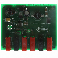
DEMOBOARD TLE 6389-2GV
Manufacturer Part Number
DEMOBOARD TLE 6389-2GV
Description
BOARD DEMO FOR TLE 6389-2GV
Manufacturer
Infineon Technologies
Datasheet
1.TLE6389-3G_V50.pdf
(38 pages)
Specifications of DEMOBOARD TLE 6389-2GV
Main Purpose
DC/DC, Step Down
Outputs And Type
1, Non-Isolated
Voltage - Output
7 ~ 15V
Current - Output
2.5A
Voltage - Input
5 ~ 60V
Regulator Topology
Buck
Frequency - Switching
360kHz
Board Type
Fully Populated
Utilized Ic / Part
TLE6389
Lead Free Status / RoHS Status
Lead free / RoHS Compliant
Power - Output
-
Other names
DEMOBOARDTLE6389-2GVIN


Datasheet Rev. 2.1
7.10.3
The crossover thresholds PFM to PWM and vice versa strongly depend on the input
voltage V
turn on and turn off delays of the external PMOS.
For more details on the PFM to PWM and PWM to PFM thresholds please refer to the
application note “TLE6389 - Determining PFM/PWM current thresholds”.
7.10.4
The choice of the output capacitor effects straight to the minimum achievable ripple
which is seen at the output of the buck converter. In continuous conduction mode the
ripple of the output voltage can be estimated by the following equation:
From the formula it is recognized that the ESR has a big influence in the total ripple at
the output, so low ESR tantalum capacitors are recommended for the application.
One other important thing to note are the requirements for the resonant frequency of the
output LC-combination. The choice of the components L and C have to meet also the
specified range given in section 3 otherwise instabilities of the regulation loop might
occur.
7.10.5
At high load currents, where the current through the inductance flows continuously, the
input capacitor is exposed to a square wave current with its duty cycle V
prevent a high ripple to the battery line a capacitor with low ESR should be used. The
maximum RMS current which the capacitor has to withstand is calculated to:
For low ESR an e.g. Al-electrolytic capacitance in parallel to an ceramic capacitance
could be used.
IN
, the Buck converter inductance L1, the sense resistor value R
PFM and PWM thresholds
Buck output capacitor (C
Input capacitor (C
I
RMS
V
Ripple
=
I
=
LOAD
IN1
) selection:
I
R
OUT
V
--------------
ESRCOUT
V
OUT
IN
) selection:
33
1
+
+
----------------------------------- -
8 f
1
-- -
3
SW
-----------------------
2 I
1
C
LOAD
I
OUT
2
SENSE
TLE 6389
2007-08-13
OUT
and the
/V
I
. To
Related parts for DEMOBOARD TLE 6389-2GV
Image
Part Number
Description
Manufacturer
Datasheet
Request
R

Part Number:
Description:
BOARD DEMO FOR TLE 6288R
Manufacturer:
Infineon Technologies
Datasheet:

Part Number:
Description:
BOARD DEMO FOR TLE 6214L
Manufacturer:
Infineon Technologies
Datasheet:

Part Number:
Description:
BOARD DEMO FOR TLE 7209-2R
Manufacturer:
Infineon Technologies
Datasheet:

Part Number:
Description:
BOARD DEMO FOR TLE 6244X
Manufacturer:
Infineon Technologies
Datasheet:

Part Number:
Description:
BOARD DEMO FOR TLE 6365 REV.4
Manufacturer:
Infineon Technologies
Datasheet:

Part Number:
Description:
BOARD DEMO FOR TLE 6389-2 GV50
Manufacturer:
Infineon Technologies
Datasheet:

Part Number:
Description:
BOARD DEMO FOR TLE 6389-3 GV50
Manufacturer:
Infineon Technologies
Datasheet:

Part Number:
Description:
BOARD DEMO FOR TLE 7230G 1.0
Manufacturer:
Infineon Technologies
Datasheet:

Part Number:
Description:
BOARD DEMO FOR TLE 6368
Manufacturer:
Infineon Technologies
Datasheet:

Part Number:
Description:
BOARD DEMO FOR TLE6208-3G
Manufacturer:
Infineon Technologies
Datasheet:

Part Number:
Description:
Manufacturer:
Infineon Technologies AG
Datasheet:
Part Number:
Description:
Manufacturer:
Infineon Technologies AG
Datasheet:
Part Number:
Description:
Manufacturer:
Infineon Technologies AG
Datasheet:
Part Number:
Description:
Manufacturer:
Infineon Technologies AG
Datasheet:
Part Number:
Description:
Manufacturer:
Infineon Technologies AG
Datasheet: