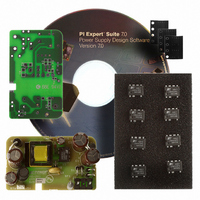
RDK-201 Power Integrations, RDK-201 Datasheet - Page 11

RDK-201
Manufacturer Part Number
RDK-201
Description
KIT REF DESIGN LINKSWITCH-CV
Manufacturer
Power Integrations
Series
LinkSwitch®-CVr
Type
MOSFET & Power Driverr
Specifications of RDK-201
Main Purpose
AC/DC, Primary Side
Outputs And Type
1, Isolated
Power - Output
6W
Voltage - Output
5V
Current - Output
1.2A
Voltage - Input
90 ~ 265VAC
Regulator Topology
Flyback
Board Type
Fully Populated
Utilized Ic / Part
LNK626
Product
Power Management Modules
Lead Free Status / RoHS Status
Lead free / RoHS Compliant
Frequency - Switching
-
Lead Free Status / Rohs Status
Lead free / RoHS Compliant
For Use With/related Products
LNK62x
Other names
596-1266
11-Nov-08
7.4 Transformer Build Diagram
7.5 Transformer Construction
Page 11 of 32
Primary Winding
Preparation
Winding 1:
Winding 2:
Winding 3:
Winding 4:
Secondary
Insulation
Insulation
Insulation
Insulation
Assembly
Feedback
Bobbin
Shield
Finish
Pull pins 7 and 10. Orient the bobbin with primary pins on the left hand side. Winding
direction is clockwise.
Start on pin 5 and wind 19 turns of bifilar item [3] from left to right terminating on pin 3.
Apply 4 layers of tape item [6].
Start on pin 2 and wind 39 turns of item [3], with tight tension, from left to right filling one
layer. Apply one layer of tape item [6]. Continue winding 38 turns of item [3] from right to
left and apply one layer of tape item [6]. Wind the remaining 38 turns of item [3] from left
to right and terminate the winding on pin 1.
Apply one layer of tape item [6].
Start on any temporary secondary pin, leaving extra wire, and wind 16 turns of trifilar
item [4] from right to left filling one layer. Secure the winding temporarily with tape and
cut the finish end of the winding. Move the starting end of the winding to pin 1.
Wrap two complete layers of tape over any leads of the previous winding.
Start on pin 9 and wind 7 turns of item [6] from right to left terminating on pin 6.
Apply 2 layers of tape item [6]
Assemble core halves and tape together after properly gapping center leg of core.
Dip Varnish
Figure 5 – Transformer Build Diagram.
Tel: +1 408 414 9200 Fax: +1 408 414 9201
RDR-201 6 W LinkSwitch-CV Adapter
Power Integrations
www.powerint.com


