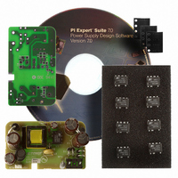
RDK-201 Power Integrations, RDK-201 Datasheet - Page 6

RDK-201
Manufacturer Part Number
RDK-201
Description
KIT REF DESIGN LINKSWITCH-CV
Manufacturer
Power Integrations
Series
LinkSwitch®-CVr
Type
MOSFET & Power Driverr
Specifications of RDK-201
Main Purpose
AC/DC, Primary Side
Outputs And Type
1, Isolated
Power - Output
6W
Voltage - Output
5V
Current - Output
1.2A
Voltage - Input
90 ~ 265VAC
Regulator Topology
Flyback
Board Type
Fully Populated
Utilized Ic / Part
LNK626
Product
Power Management Modules
Lead Free Status / RoHS Status
Lead free / RoHS Compliant
Frequency - Switching
-
Lead Free Status / Rohs Status
Lead free / RoHS Compliant
For Use With/related Products
LNK62x
Other names
596-1266
RDR-201 6 W LinkSwitch-CV Adapter
4 Circuit Description
The schematic in Figure 2 shows an adapter design using the LNK625PG that provides
very tight constant voltage (CV) performance. The circuit is designed to operate from
90 VAC to 265 VAC input, with an output voltage of 5 V providing a maximum load
current of 1.2 A. It consumes very little standby power and uses no Y-Capacitor to meet
stringent EMI requirements. The adapter also meets and exceeds both CEC and Energy
Star 2.0 regulations.
4.1 Input and EMI Filtering
Diodes D1 through D4 form a full wave rectifier. The rectified DC is then filtered by
capacitors C1 and C2. Inductor L1 forms a pi (π) filter with capacitors C1 and C2 which
helps to reduce differential EMI noise.
frequency jitter provided in U1 and transformer E-Shield techniques, provide a generous
EMI margin without the need for a Y capacitor across the primary and secondary
windings of transformer T1.
4.2 LinkSwitch-CV Device
The LinkSwitch-CV family of devices has been developed to cost effectively replace all
existing solutions in low power adapter applications. It is optimized for constant voltage
(CV) adapter applications while using minimal external parts including the complete
elimination of the optocoupler and shunt regulator.
The LNK625PG monolithically integrates the 700 V power MOSFET switch and
controller, which consists of an oscillator, feedback (sense and logic) circuit, 6 V
regulator, BYPASS pin programming functions, over-temperature protection, frequency
jittering, current limit circuit and leading-edge blanking.
The LNK625PG also provides a sophisticated range of protection features including auto-
restart for control loop component open/short circuit faults and output short circuit
conditions. The use of a low auto-restart on time reduces the power delivered by more
than 95 % for output short circuits and control loop faults. Accurate hysteretic thermal
shutdown ensures safe average PCB temperatures under all conditions. Extended
creepage distance between high and low voltage pins prevent arcing and helps meet
safety requirements. LinkSwitch-CV also can be used without a bias winding as the IC is
completely self biased.
4.3 Primary Circuit
During U1’s on time current flows through the primary winding of transformer T1 and
stores energy in its magnetic field. During U1’s off time, the energy stored in the
transformer is transferred to the secondary side, delivering current to both the output
capacitors and the load.
Power Integrations
Tel: +1 408 414 9200 Fax: +1 408 414 9201
www.powerint.com
This filtering, together with the integrated switching
Page 6 of 32
11-Nov-08


