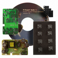
RDK-201 Power Integrations, RDK-201 Datasheet - Page 4

RDK-201
Manufacturer Part Number
RDK-201
Description
KIT REF DESIGN LINKSWITCH-CV
Manufacturer
Power Integrations
Series
LinkSwitch®-CVr
Type
MOSFET & Power Driverr
Specifications of RDK-201
Main Purpose
AC/DC, Primary Side
Outputs And Type
1, Isolated
Power - Output
6W
Voltage - Output
5V
Current - Output
1.2A
Voltage - Input
90 ~ 265VAC
Regulator Topology
Flyback
Board Type
Fully Populated
Utilized Ic / Part
LNK626
Product
Power Management Modules
Lead Free Status / RoHS Status
Lead free / RoHS Compliant
Frequency - Switching
-
Lead Free Status / Rohs Status
Lead free / RoHS Compliant
For Use With/related Products
LNK62x
Other names
596-1266
RDR-201 6 W LinkSwitch-CV Adapter
2 Power Supply Specification
Input
Voltage
Frequency
No-load Input Power (230 VAC)
Output
Output Voltage
Output Ripple Voltage
Output Current
Total Output Power
Continuous Output Power
Efficiency
Full Load
Required average efficiency at
25, 50, 75 and 100 % of P
Measured average efficiency
Environmental
Conducted EMI
Safety
Line Surge
Ambient Temperature
Differential Mode (L1-L2)
Common mode (L1/L2-PE)
Description
Power Integrations
Tel: +1 408 414 9200 Fax: +1 408 414 9201
www.powerint.com
OUT
Symbol
V
η
V
P
T
f
η
RIPPLE
I
V
LINE
ES2.0
OUT
AMB
OUT
OUT
CBL
η
IN
4.75
Min
Designed to meet IEC950 / UL1950
90
47
76
70
76
73
0
6
1
2
0
Meets CISPR22B / EN55022B
50/60
Typ
100
5.0
71
25
Class II
Max
5.25
265
1.2
64
90
40
Units
VAC
mW
mV
Hz
kV
kV
o
W
%
%
%
%
%
V
A
C
At end of 6 ft, 315 mΩ output cable
At end of 6 ft, 315 mΩ output cable
1.2/50 µs surge, IEC 1000-4-5,
Free convection, sea level
Per ENERGY STAR V2.0
Measured at P
Differential Mode: 2 Ω
Common Mode: 12 Ω
Series Impedance:
20 MHz bandwidth
At board terminals
2 Wire – no P.E.
Comment
At board
± 5%
Page 4 of 32
11-Nov-08
OUT
25
o
C


