STEVAL-ISA023V2 STMicroelectronics, STEVAL-ISA023V2 Datasheet - Page 3
STEVAL-ISA023V2
Manufacturer Part Number
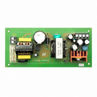
STEVAL-ISA023V2
Description
EVAL BOARD 24W NEG OUT VIPER53E
Manufacturer
STMicroelectronics
Series
VIPER™r
Type
AC/DC Switching Convertersr
Specifications of STEVAL-ISA023V2
Mfg Application Notes
VIPer53EDIP - AppNote
Design Resources
STEVAL-ISA023V2 Gerber Files STEVAL-ISA023V2 Schematic STEVAL-ISA023V2 Bill of Materials
Main Purpose
AC/DC, Primary Side
Outputs And Type
2, Isolated
Power - Output
24W
Voltage - Output
-5V, -12V
Current - Output
3A, 800mA
Voltage - Input
90 ~ 265VAC
Regulator Topology
Flyback
Frequency - Switching
60kHz
Board Type
Fully Populated
Utilized Ic / Part
VIPer53
Input Voltage
90 V to 265 V
Output Voltage
- 5 V, - 12 V
Product
Power Management Modules
Silicon Manufacturer
ST Micro
Silicon Core Number
VIPer53-E
Kit Application Type
Power Management
Application Sub Type
SMPS
Kit Contents
Board
Lead Free Status / RoHS Status
Lead free / RoHS Compliant
For Use With/related Products
VIPer53-E
Other names
497-5866
Available stocks
Company
Part Number
Manufacturer
Quantity
Price
Company:

Part Number:
STEVAL-ISA023V2
Manufacturer:
STMicroelectronics
Quantity:
1


VIPer53 - E
1
1.1
1.2
Electrical data
Maximum rating
Stressing the device above the rating listed in the “Absolute Maximum Ratings” table may
cause permanent damage to the device. These are stress ratings only and operation of the
device at these or any other conditions above those indicated in the Operating sections of
this specification is not implied. Exposure to Absolute Maximum Rating conditions for
extended periods may affect device reliability. Refer also to the STMicroelectronics SURE
Program and other relevant quality documents.
Table 1.
1. In order to improve the ruggedness of the device versus eventual drain overvoltages, a resistance of 1k
Thermal data
Table 2.
1. When mounted on a standard single-sided FR4 board with 50mm² of Cu (at least 35 mm thick) connected
2. When mounted on a standard single-sided FR4 board with 50mm² of Cu (at least 35 mm thick) connected
Symbol
Symbol
I
R
R
V
I
V
T
COMP
should be inserted in series with the TOVL pin.\
to the DRAIN pin.
to the device tab.
V
V
TOVL
thJC
OSC
T
thJA
T
STG
ESD
I
DS
DD
D
C
J
Thermal Resistance Junction-case
Thermal Resistance Ambient-case
Continuous drain source voltage (T
Continuous drain current
Supply voltage
OSC input voltage range
COMP and TOVL input current range
Electrostatic discharge:
Machine model (R = 0 ; C = 200pF)
Charged device model
Junction operating temperature
Case operating temperature
Storage temperature
Absolute maximum rating
Thermal data
Parameter
Parameter
J
= 25 ... 125°C)
(1)
Max
Max
PowerSO-10
(1)
60
2
(1)
Internally limited
Internally limited
-0.3 ... 620
-40 to 150
-55 to 150
0 ... V
0 ... 19
-2 ... 2
Value
DIP-8
200
1.5
Electrical data
20
80
DD
(2)
Unit
Unit
C/W
C/W
mA
kV
V
A
V
V
V
C
C
C
3/36
Related parts for STEVAL-ISA023V2
Image
Part Number
Description
Manufacturer
Datasheet
Request
R

Part Number:
Description:
BOARD RGB CTR ST7,STP08C596MTR
Manufacturer:
STMicroelectronics
Datasheet:

Part Number:
Description:
Power Management IC Development Tools Full Speed USB to RS232 Bridge Demo
Manufacturer:
STMicroelectronics
Datasheet:
Part Number:
Description:
Power Management IC Development Tools 2.5W solar eval BRD USB SPV1040 LD39050
Manufacturer:
STMicroelectronics
Datasheet:

Part Number:
Description:
BOARD EVAL FOR MEMS SENSORS
Manufacturer:
STMicroelectronics
Datasheet:

Part Number:
Description:
KIT DEV STARTER ST10F276Z5
Manufacturer:
STMicroelectronics
Datasheet:

Part Number:
Description:
BOARD EVAL HDMI $ VIDEO SWITCH
Manufacturer:
STMicroelectronics
Datasheet:

Part Number:
Description:
BOARD DEMO ACCELEROMETER DIL24
Manufacturer:
STMicroelectronics
Datasheet:

Part Number:
Description:
BOARD STLM75/STDS75/ST72F651
Manufacturer:
STMicroelectronics
Datasheet:

Part Number:
Description:
EVAL BOARD 3AXIS MEMS ACCELLRMTR
Manufacturer:
STMicroelectronics
Datasheet:

Part Number:
Description:
BOARD EVAL 8BIT MICRO + TDE1708
Manufacturer:
STMicroelectronics
Datasheet:
Part Number:
Description:
STMicroelectronics [RIPPLE-CARRY BINARY COUNTER/DIVIDERS]
Manufacturer:
STMicroelectronics
Datasheet:
Part Number:
Description:
STMicroelectronics [LIQUID-CRYSTAL DISPLAY DRIVERS]
Manufacturer:
STMicroelectronics
Datasheet:
Part Number:
Description:
BOARD EVAL FOR MEMS SENSORS
Manufacturer:
STMicroelectronics
Datasheet: