EVL6566A-75WADP STMicroelectronics, EVL6566A-75WADP Datasheet - Page 4
EVL6566A-75WADP
Manufacturer Part Number
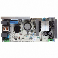
EVL6566A-75WADP
Description
BOARD EVAL FOR L6566A
Manufacturer
STMicroelectronics
Type
Power Factor Correctionr
Datasheets
1.L6566ATR.pdf
(51 pages)
2.TSM1014IDT.pdf
(10 pages)
3.L6563ATR.pdf
(39 pages)
4.EVL6566A-75WADP.pdf
(8 pages)
Specifications of EVL6566A-75WADP
Main Purpose
AC/DC, Primary and Secondary Side with PFC
Outputs And Type
1, Isolated
Power - Output
75W
Voltage - Output
19V
Current - Output
4A
Voltage - Input
90 ~ 264VAC
Frequency - Switching
65kHz
Board Type
Fully Populated
Utilized Ic / Part
L6563, L6566A, TSM1014
Input Voltage
90 V to 264 V
Output Voltage
19 V
Dimensions
78 mm x 174 mm
Product
Power Management Modules
Lead Free Status / RoHS Status
Lead free / RoHS Compliant
Regulator Topology
-
Lead Free Status / Rohs Status
Lead free / RoHS Compliant
For Use With/related Products
L6563, L6566A
Other names
497-6449
Available stocks
Company
Part Number
Manufacturer
Quantity
Price


Description
1.1
1.2
Table 2. Pin description
4/39
Pin N°
1
2
3
4
5
COMP
Name
MULT
VFF
INV
Pin connection
Figure 3.
Pin description
CS
Inverting input of the error amplifier. The information on the output voltage of the PFC pre-
regulator is fed into the pin through a resistor divider.
The pin normally features high impedance but, if the tracking boost function is used, an
internal current generator programmed by TBO (pin 6) is activated. It sinks current from the
pin to change the output voltage so that it tracks the mains voltage.
Output of the error amplifier. A compensation network is placed between this pin and INV
(pin 1) to achieve stability of the voltage control loop and ensure high power factor and low
THD.
Main input to the multiplier. This pin is connected to the rectified mains voltage via a
resistor divider and provides the sinusoidal reference to the current loop. The voltage on
this pin is used also to derive the information on the RMS mains voltage.
Input to the PWM comparator. The current flowing in the MOSFET is sensed through a
resistor, the resulting voltage is applied to this pin and compared with an internal reference
to determine MOSFET’s turn-off.
A second comparison level at 1.7V detects abnormal currents (e.g. due to boost inductor
saturation) and, on this occurrence, shuts down the IC, reduces its consumption almost to
the start-up level and asserts PWM_LATCH (pin 8) high. This function is not present in the
L6563A.
Second input to the multiplier for 1/V
connected from the pin to GND. They complete the internal peak-holding circuit that
derives the information on the RMS mains voltage. The voltage at this pin, a DC level equal
to the peak voltage at pin MULT (pin 3), compensates the control loop gain dependence on
the mains voltage. Never connect the pin directly to GND.
Pin connection (top view)
PFC_OK
COMP
MULT
TBO
VFF
INV
CS
1
2
3
4
5
6
7
2
function. A capacitor and a parallel resistor must be
Description
14
13
12
11
10
9
8
Vcc
GD
GND
ZCD
RUN
PWM_STOP
PWM_LATCH
L6563 - L6563A
Related parts for EVL6566A-75WADP
Image
Part Number
Description
Manufacturer
Datasheet
Request
R

Part Number:
Description:
BOARD DEMO FOR L6563/LL6566A
Manufacturer:
STMicroelectronics
Datasheet:

Part Number:
Description:
STMicroelectronics [RIPPLE-CARRY BINARY COUNTER/DIVIDERS]
Manufacturer:
STMicroelectronics
Datasheet:
Part Number:
Description:
STMicroelectronics [LIQUID-CRYSTAL DISPLAY DRIVERS]
Manufacturer:
STMicroelectronics
Datasheet:

Part Number:
Description:
BOARD EVAL FOR MEMS SENSORS
Manufacturer:
STMicroelectronics
Datasheet:
Part Number:
Description:
NPN TRANSISTOR POWER MODULE
Manufacturer:
STMicroelectronics
Datasheet:
Part Number:
Description:
TURBOSWITCH ULTRA-FAST HIGH VOLTAGE DIODE
Manufacturer:
STMicroelectronics
Datasheet:
Part Number:
Description:
Manufacturer:
STMicroelectronics
Datasheet:
Part Number:
Description:
DIODE / SCR MODULE
Manufacturer:
STMicroelectronics
Datasheet:
Part Number:
Description:
DIODE / SCR MODULE
Manufacturer:
STMicroelectronics
Datasheet:
Part Number:
Description:
Search -----> STE16N100
Manufacturer:
STMicroelectronics
Datasheet:
Part Number:
Description:
Search ---> STE53NA50
Manufacturer:
STMicroelectronics
Datasheet:
Part Number:
Description:
NPN Transistor Power Module
Manufacturer:
STMicroelectronics
Datasheet: