EVL6566A-75WES4 STMicroelectronics, EVL6566A-75WES4 Datasheet - Page 23
EVL6566A-75WES4
Manufacturer Part Number
EVL6566A-75WES4
Description
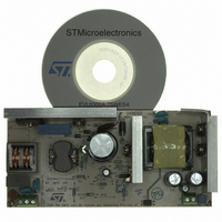
BOARD DEMO FOR L6563/LL6566A
Manufacturer
STMicroelectronics
Type
Power Factor Correctionr
Specifications of EVL6566A-75WES4
Main Purpose
AC/DC, Primary and Secondary Side with PFC
Outputs And Type
1, Isolated
Power - Output
75W
Voltage - Output
19V
Current - Output
4A
Voltage - Input
90 ~ 264VAC
Regulator Topology
Flyback
Board Type
Fully Populated
Utilized Ic / Part
L6563, L6566A, TSM1014
Input Voltage
90 V to 264 V
Output Voltage
19 V
Dimensions
78 mm x 170 mm
Product
Power Management Modules
Lead Free Status / RoHS Status
Lead free / RoHS Compliant
Frequency - Switching
-
Lead Free Status / Rohs Status
Lead free / RoHS Compliant
For Use With/related Products
L6563S, L6566A
Other names
497-8834
Available stocks
Company
Part Number
Manufacturer
Quantity
Price


L6566A
Figure 10. Operation of ZCD, triggering and oscillator blocks (QR option active)
Arm/Trigger
PWM latch
PWM latch
ON-enable
Oscillator
Reset
blanking
(pin 11)
ramp
Set
(pin 4)
ZCD
time
ZCD
100 mV
GD
50 mV
armed
The operation described so far under different operating conditions for the converter is
illustrated in the timing diagrams of
If the FF option is selected the operation will be exactly equal to that of a standard current-
mode PWM controller. It will work at a frequency fsw = fosc; both DCM and CCM
transformer's operation are possible, depending on the operating conditions (input voltage
and output load) and on the design of the power stage. The MOSFET is turned on at the
beginning of each oscillator cycle and is turned off as the voltage on the current sense pin
reaches an internal reference set by the Line Feedforward block. The maximum duty cycle is
limited at 70 % minimum. The signal on the ZCD pin in this case is used only for detecting
feedback loop failures (see
trigger
a) full load
Arm/Trigger
ON-enable
PWM latch
PWM latch
Oscillator
Reset
blanking
(pin 11)
Set
ramp
(pin 4)
ZCD
ZCD
time
100 mV
GD
50 mV
Section 5.11: OVP block on page 35
Figure 10
b) light load
.
Arm/Trigger
ON-enable
PWM latch
PWM latch
Oscillator
Reset
blanking
(pin 11)
ramp
Set
(pin 4)
ZCD
ZCD
time
100 mV
GD
50 mV
).
Application information
c) start-up
23/51
Related parts for EVL6566A-75WES4
Image
Part Number
Description
Manufacturer
Datasheet
Request
R

Part Number:
Description:
BOARD EVAL FOR L6566A
Manufacturer:
STMicroelectronics
Datasheet:

Part Number:
Description:
STMicroelectronics [RIPPLE-CARRY BINARY COUNTER/DIVIDERS]
Manufacturer:
STMicroelectronics
Datasheet:
Part Number:
Description:
STMicroelectronics [LIQUID-CRYSTAL DISPLAY DRIVERS]
Manufacturer:
STMicroelectronics
Datasheet:

Part Number:
Description:
BOARD EVAL FOR MEMS SENSORS
Manufacturer:
STMicroelectronics
Datasheet:
Part Number:
Description:
NPN TRANSISTOR POWER MODULE
Manufacturer:
STMicroelectronics
Datasheet:
Part Number:
Description:
TURBOSWITCH ULTRA-FAST HIGH VOLTAGE DIODE
Manufacturer:
STMicroelectronics
Datasheet:
Part Number:
Description:
Manufacturer:
STMicroelectronics
Datasheet:
Part Number:
Description:
DIODE / SCR MODULE
Manufacturer:
STMicroelectronics
Datasheet:
Part Number:
Description:
DIODE / SCR MODULE
Manufacturer:
STMicroelectronics
Datasheet:
Part Number:
Description:
Search -----> STE16N100
Manufacturer:
STMicroelectronics
Datasheet:
Part Number:
Description:
Search ---> STE53NA50
Manufacturer:
STMicroelectronics
Datasheet:
Part Number:
Description:
NPN Transistor Power Module
Manufacturer:
STMicroelectronics
Datasheet: